-16-
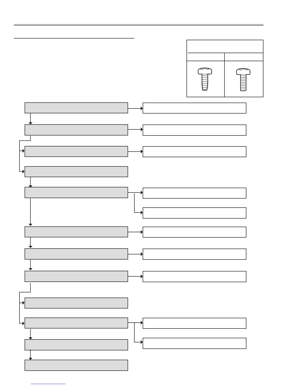
Mechanical disassembly flow chart
1 Cabinet front cover removal
2 Cabinet top removal
3 Control assy and filter cover removal
4 Main board removal
5 Cabinet back & lamp cover removal
6 Power box removal
8 Optical unit removal
9 Cabinet front removal
10 Filter box removal
11 Fan (FN902, FN903, FN908) & duct removal
1-1 Cabinet front disassembly
2-1 LED board removal
3-1 Control board fan (FN907) disassembly
5-1 AV board removal
5-2 Fans (FN904, FN905, FN906) removal
6-1 Power box disassembly
8-1 Lens shift motor assy removal
10-1 Filter box and fan(FN901) disassembly-1
10-2 Filter box disassembly-2
Mechanical disassembly should be made by following procedures chart.
Following steps show the basic procedures, therefore unnecessary step may
be ignored.
Caution:
The parts and screws should be placed exactly the same position as the origi-
nal otherwise it may cause loss of performance and product safety.
The wiring method of the leads and ferrite cores should be returned exactly the
same state as the original, otherwise it may cause lose of performance and
product safety.
Screws Expression
(Type Diameter x Length) mm
T type M Type
Mechanical Disassembly
7 Ballast box removal
7-1 Ballast box disassembly
12 Lens shift cover and shield base removal

 Loading...


