-22-
Mechanical Disassembly
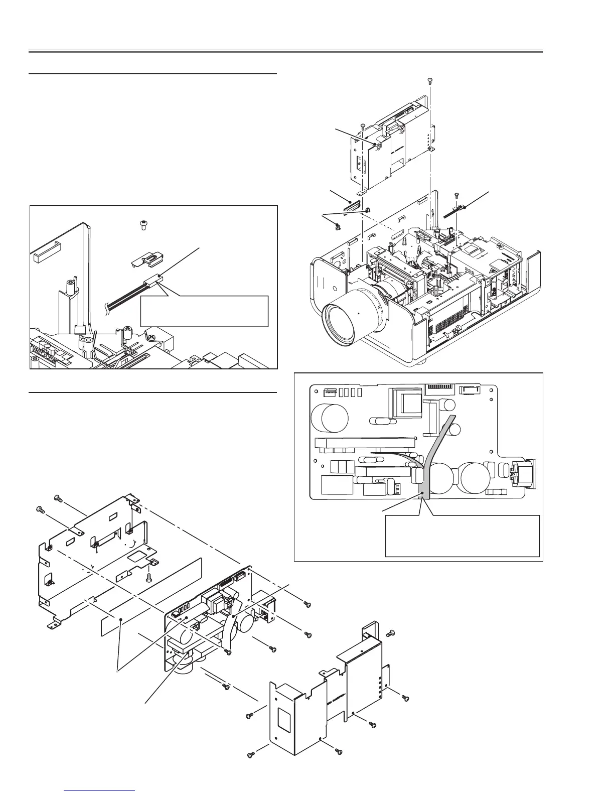
6 Power Box removal
1 Remove 3 covers A and B on the cabinet.
2 Remove 1 screw C (M3x6) and take thermal protector
(SW905) off
3 Disconnect the socket D (K6B) on the power board.
4 Remove 2 screws E (M4x8) and take the power box
upward off.
6-1 Power box disassembly
1 Remove 6 screws F (M3x6) and take the power box
cover off.
2 Remove 5 screws G (M3x6), 1 screw H (M4x8), 2
screws J (M2.8x4) and take the power board off.
E
E
C
B
A
D
Thermal protec-
tor (SW905)
F
F
F
F
F
F
G
G
G
G
G
H
Insulation sheet
Isolation sheet
Power board
Isolation sheet
Note:
The isolation sheet must be placed
as shown in the figure above.
J
Thermal protector
(SW905)
Note: Mount as the printed
mark comes up side.

 Loading...


