-32-
Optical Parts Disassembly
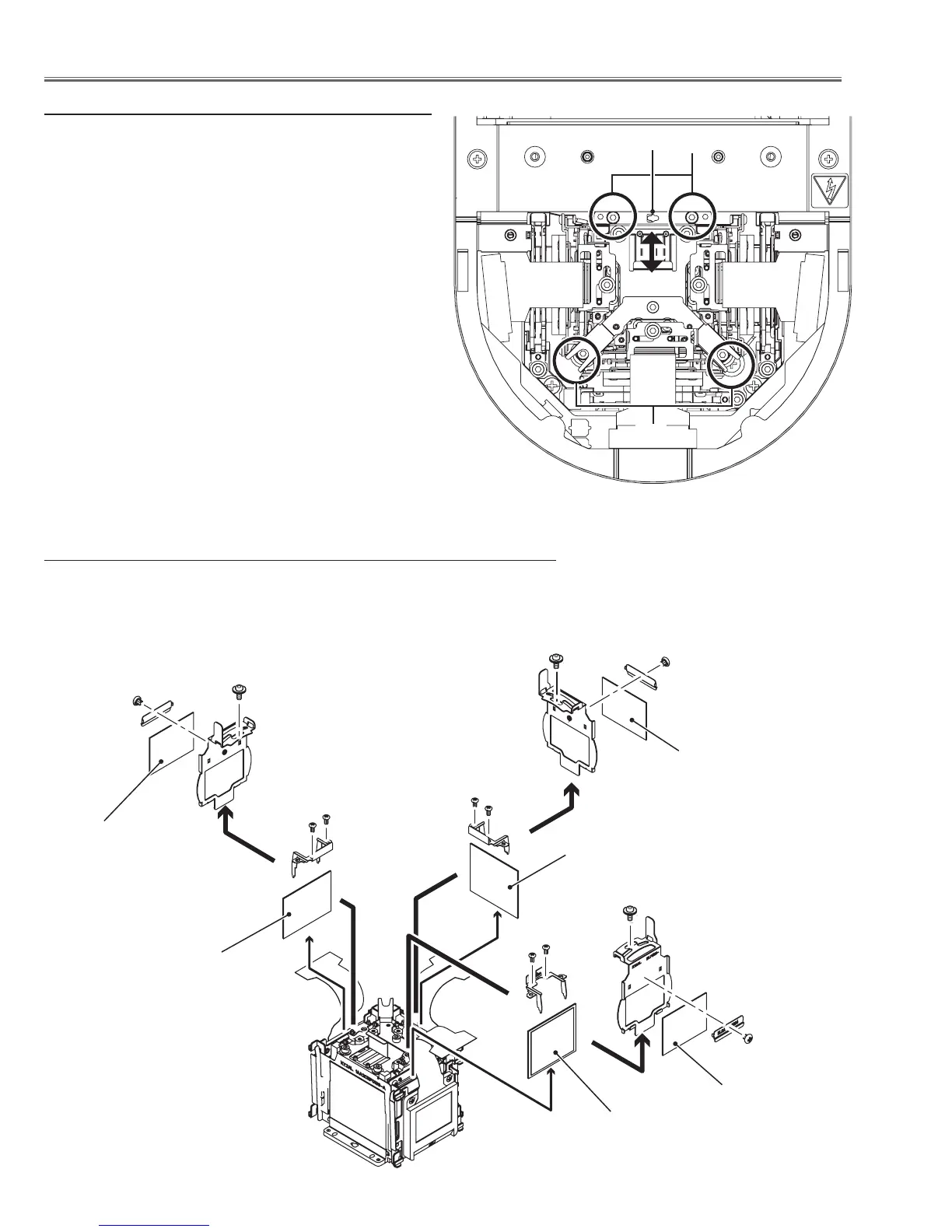
2-1 Polarized glass (OUT) and optical filter (ICV) removal
1 Remove 1 screw D (M2.5x6) on each holder and take the optical filter
(ICV) assy upward off.
2 Remove 2 screws E (M2x4) to remove the holder and then take the polar-
ized glass (OUT) upward off.
D
D
D
Polarized glass(OUT/B)1
Optical filter (ICV)
Polarized glass(OUT/G)1
Optical filter (ICV)
Polarized glass(OUT/R)1
(Green)
(Red)
(Blue)
Note on LCD panel/prism assy mounting
After replacing or installing the LCD panel/prism assy,
please make sure to obtain the best focus in both TELE
and WIDE zoom. If the focus adjustment is required,
please adjust the positioning of LCD panel/prism assy
following to the procedure below.
Focus adjustment:
1 Loosen 4 screws A on the LCD Panel/Prism ass’y with
2.0 mm hex driver.
2 Turn the projector on and project the image with WIDE
zoom, and adjust the FOCUS control to obtain the best
focus.
3 Turn the ZOOM control to the TELE position.
4 Insert a flat screw driver into the slot B and move the
LCD panel/prism assy backward or forward by turning
the screwdriver left or right to obtain the proper focus.
Confirm the focus at TELE and WIDE zoom.
5 Tighten 4 screws A to fix the LCD panel/prism assy.
A
A
E
E
E
Optical filter (ICV)
(M2x2)
(M2x2)
(M2x2)
B

 Loading...


