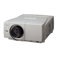
Do you have a question about the Sanyo PLC-XF60A and is the answer not in the manual?
| Vertical scan range | 48 - 120 Hz |
|---|---|
| Horizontal scan range | 15 - 120 kHz |
| Projection technology | LCD |
| Contrast ratio (typical) | 1300:1 |
| Projector native resolution | XGA (1024x768) |
| Keystone correction, vertical | 40 ° |
| Keystone correction, horizontal | 30 ° |
| Aspect ratio | 4:3 |
| Compatibility | UXGA/SXGA/XGA/SVGA/VGA/Mac |
| Dimensions (WxDxH) | 518 x 252 x 606 mm |
| Power requirements | AC 100-240 V, 50/60 Hz |
| Lamp type | UHP |
| Lamp power | 300 W |
| Light source type | Lamp |
| Noise level | 39 dB |
| Dot clock scanning frequency | 230 MHz |
| Microphone in | Yes |
| S-Video inputs quantity | 1 |
| Power consumption (typical) | 900 W |
| Operating temperature (T-T) | 5 - 35 °C |
| Weight | 24000 g |
|---|
Outlines essential safety measures to be followed during servicing.
Warns service personnel about specific hazards and precautions.
Provides important notices regarding product safety for components.
Explains the fuse protection circuit and its location.
Describes the mechanical switches that detect lamp cover mounting.
Details sensors for monitoring and air filter clog detection.
Details the thermal switches used for internal temperature monitoring.
Explains detection circuits for power failure and fan lock.
Warns about safety precautions during lamp replacement.
Step-by-step instructions for replacing the LCD panel.
Procedure to reset the projector's PIN code to the factory default.
Table indicating necessary adjustments after replacing specific parts.
Guide for performing the optical center adjustment.
Procedure for adjusting the integrator-in angle.
Procedure for aligning the Mirror-R to overlap projected images.
Procedure for adjusting the relay lens-B for color offset.
Procedure for adjusting the integrator-out and integrator-in.
Procedure for adjusting the white uniformity of the screen.
Procedure for adjusting contrast for optimal brightness and color uniformity.
Explains the reference standard and adjustments for convergence.
Procedure for adjusting the back focus of the LCD panel/prism assembly.
Procedure for removing color shading on the screen.
Preparation and procedures for adjusting LCD panel convergence.
Instructions for entering and operating the service adjustment menu.
Table listing service adjustments, group numbers, item numbers, functions, ranges, and initial values.
Steps to access the service mode.
Steps to select, adjust, and change service data.
Instructions for exiting the service mode.
Information and cautions regarding replacing the memory IC.
Details adjustments for fan control in normal and dim modes.
Steps for automatic adjustment of PC and AV input signals.
Procedure for adjusting PC and AV gain.
Procedure for adjusting AV white balance with 2-lamp mode.
Diagram showing test points and their locations on the POWER(DC) Board.
Procedure for adjusting common center by minimum flicker.
Procedures for adjusting white balance for Lamp1.
Procedure for adjusting PC white balance.
Procedures for adjusting white balance for Lamp2.
Procedure for adjusting gamma shift for G, R, and B signals.
Procedure for adjusting AV white balance.
Explains how input signals are received, selected, and decoded.
Details the digital-to-analog conversion and drive signals for LCD panels.
Explains fan power supplies and the function of temperature/airflow sensors.
Explains motor control signals for zoom, focus, lens shift, and shutter.
Explains input signal selection and remote control signal reception.
Troubleshooting section for no picture issues.
Details temperature sensors role in fan speed and projector shutdown.
Details motor drive signals and lens position monitoring.
Describes airflow, thermal, and shutter sensors and their functions.
Describes shutter motor control signals, sensor switches, and status.
Troubleshooting for no power issues related to fan failure.
Explains the lamp driving circuit, power supply, and cover switches.
Explains protection circuits for power failure, fan failure, and temperature failure.
Explains how LEDs on the cabinet indicate abnormal parts or places.
Procedure for diagnosing power failures using RS-232C serial port.
Details the circuit for controlling lamp on/off signals.
Table mapping detecting signals to failure circuits and parts.
Describes the power signals for lamp ballast and control circuits.
Lists power failure detection signals related to the MAIN board.
Explains how switches cut off power to the lamp ballast.
Lists power failure detection signals related to the LCD Drive Board.
Describes thermal switches causing shutdown on high temperature.
Troubleshooting for issues related to no power.
Specific checks for troubleshooting no power issues.
Shows LED indications for lamp failures and related parts.
Explains how lamp cover switches prevent the projector from turning on.
 Loading...