14 Weigh Cell Operating Instructions
Installation
5.3.1 Installation Instructions
During use, always ensure that the serial numbers of the
weigh cell and electronics match!
The corresponding cable must be securely inserted into
the electronics and screwed into place before initial
startup.
The device is designed to deliver reliable weighing
results when installed properly.
The device works precisely and quickly if the following
points in particular are observed during system
development and installation:
— Avoid exposure to extreme heat, e.g., from electronic
components, heaters or sunlight.
— Protect the device from direct drafts.
— Avoid shocks and vibrations, e.g., from motors or
valves, during weighing.
— Protect the device from aggressive chemical vapors.
— Do not expose to extreme moisture.
— Do not expose to magnetic influences.
5.4 Acclimatization
When a cold device is brought into a warm environment:
The temperature difference can lead to condensation
from humidity in the device (moisture formation).
Moisture in the device can lead to malfunctions.
Procedure
t Allow the device to acclimatize at the installation site
(for the acclimatization duration see Chapter “13.5
Acclimatization Before Power Supply”, page 52).
The device must be disconnected from the power
supply during that time.
5.5 Warm-up Time
After connection to the power
supply, the warm-up time
must be observed in order to
comply with the information
from the specifications. This
will be influenced by the sys-
tem used. The guide values for
the weigh cells are specified in
the “Technical Data” (see 13.6,
52) section.
However, this guide value
must be verified by the user in
the respective system/use
situation.
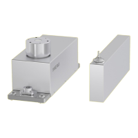
5.6 Leveling the Load Receptor for
User-specific Load Holder
(Except for WZB25-NC)
Procedure
t Apply the spacer
-
tor (2).
t Secure the load recep-
tor with the enclosed
screw (for torques, see
Chapter “5.11 Maxi-
mum Load on the Pan
Support”, page 16).
t Remove the screw (4).
t Use the screws (3) to
radially align and level
the load receptor
(limited height
adjustment).
t Secure the load
receptor again with the
screw (4) (for torques,
see Chapter “5.11
Maximum Load on the
Pan Support”,
page 16).
1
2
3
3
3
4
 Loading...

