Weigh Cell Operating Instructions 15
Installation
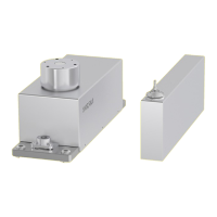
t If required: Screw the
user-specific load
holder onto the thread
(5) of the load receptor
(for torques, see
Chapter “5.11
Maximum Load on the
Pan Support”,
page 16).
t The user-specific load holder must be rigid and be
securely screwed to the load receptor.
5.7 Leveling Weigh Cells (Leveling
Feet Optional)
Purpose
— To compensate for uneven areas at the place of
installation.
— To ensure that the weigh cell is placed in a perfectly
horizontal position for consistently reproducible
weighing results.
— Always level the weigh cell again whenever it has
been moved to a different location.
Procedure
t Level the weigh cell
using the foot screws.
Turn the foot screws
until the air bubble is
centered in the level
indicator.
5.8 Securely Installing Weigh Cells
Requirement
The installation of the weigh cell is complete.
Procedure
t Adjust the weigh cell
horizontally in the
system at the fixed
location.
t Fasten M6 screws to
the base plate of the
weigh cell (1): Torque
t Secure M4 screws to
the threads of a user-
specific fastening
frame from the
t NOTICE Do not re-
move the sleeve.
5.9 Establishing the Weigh Cell –
Electronics Unit Connection
NOTICE
Mixing up the weigh cell and electronics unit may result
in malfunctions:
t Ensure that the serial numbers are the same.
t Only connect device parts that belong together.
t Insert the plug of the connection cable into the
socket of the electronics unit.
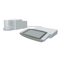
5.10 Connecting the Optional
Display Unit
The YRD01 control unit can be connected while
operation is ongoing (hot plug-in).
t Insert the connection plug into the USB-C
connection of the electronics unit.
1
2
5
5
 Loading...