10 GSM-X SATEL
De
to common ground when in active state).
%).
scription of terminals
IN1…IN4 – inputs.
COM – common ground.
OC1...OC4 – OC type outputs (shorted
AUX – +12 V DC power output.
+12V – power input (12 V DC ±15
– protective terminal of telephone communicator (to be connected only to the PE
R-1, T-1
When m es the DC voltage polarity on
protective earth circuit of 230 V AC mains).
– analog telephone line output (for connecting a telephone or a device fitted with
telephone communicator, e.g. control panel).
aking a telephone call, the module chang
telephone line output (T-1 and R-1 terminals), thus enabling individual charging of the
phone calls.
RING, TIP – analog telephone line input (from telephone provider).
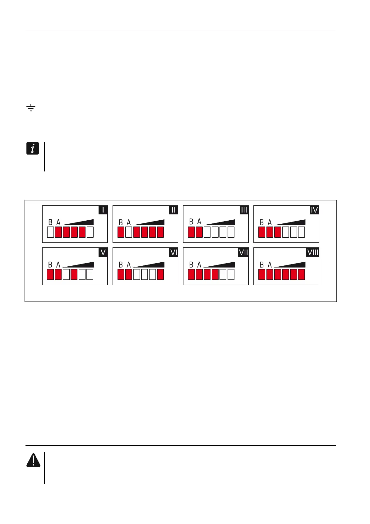
4.1.1 LED indicator
Fig. 7. Examples of LED indicated statuses.
ing on; signal level: I (LED A is flashing, the other LEDs are ON) – GPRS transmission is go
3.
II (LED B is flashing, the other LEDs are ON) – SMS message is being sent, module is calling
(AUDIO connection or CLIP message); signal level: 4.
III (LEDs are flashing) – logging into GSM network.
IV (LEDs are flashing) – logging into GSM network has failed; missing SIM card.
en blocked
VII
5. Installation
V (LEDs are flashing) – logging into GSM network has failed; incorrect PIN code.
VI (LEDs are flashing) – logging into GSM network has failed; SIM card has be
after three attempts to use an invalid PIN code (PUK code must be used to unblock the
SIM card).
(LEDs are flashing) – GSM phone is disabled (see “SIM 1 / SIM 2” option p. 27).
VIII (LEDs are flashing) – module waiting for configuration settings to be loaded.
Disconnect power before making any electrical connections.
It is not advisable to power up the module if the antenna is not connected.

 Loading...