14 GSM-X SATEL
5.5 Connecting the devices to the inputs and outputs
1. Connect the devices whose operation is to be monitored by the module to the input
terminals.
2. Connect the devices which are to be controlled by the module to the terminals of OC type
outputs.
The sum of currents drawn by devices powered from the AUX output must not exceed
300 mA.
5.6 Connecting the RS-232 port
If the module is to work in conjunction with the INTEGRA / INTEGRA Plus control panel,
connect together the RS-232 ports on module and control panel. To connect the module
PIN5 connector to the control panel RJ connector, use the RJ/PIN5 cable offered by SATEL.
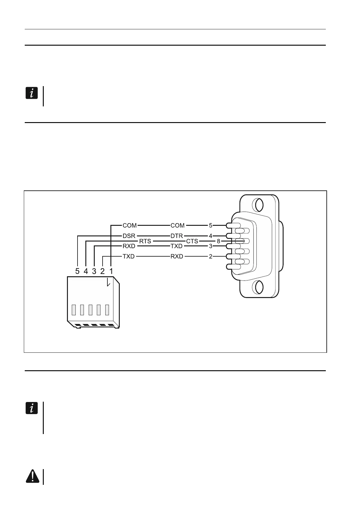
If the module is to work in conjunction with the STAM-2 monitoring station, connect the
module RS-232 port to the port of computer on which the cards are installed. If the computer
has a RS-232 port, make a connection according to Fig. 12. If the computer has a USB port,
use the USB-RS converter available from SATEL.
Fig. 12. Connecting the RS-232 ports on module and computer. Shown on the left is
PIN-5 plug. Shown on the right is DB-9 female connector (solder side view).
5.7 Connecting the power supply and starting the module
The module may be powered from the control panel, from an expander with power supply, or
from a power supply unit with current limitation up to 3 A. SATEL offers power supplies (e.g.
APS-612), which can be connected to the APS connector on the electronics board.
When the supply voltage drops below 9.8 V, restart of the module occurs.
The required output current of power supply is at least 500 mA (provided that no
device is powered from the module AUX output).
1. Depending on the selected method of module powering, connect the power supply unit to
the APS connector or connect the power leads to the +12V and COM terminals (use
flexible conductors with a cross-section of 0.5-0.75 mm
2
, or rigid conductors with a cross-
section of 1-2.5 mm
2
).
Never connect power supply to APS connector and terminals at the same time.
 Loading...