4 Checking and Performing Printer Adjustments
55
CL4NX/CL6NX Service Manual
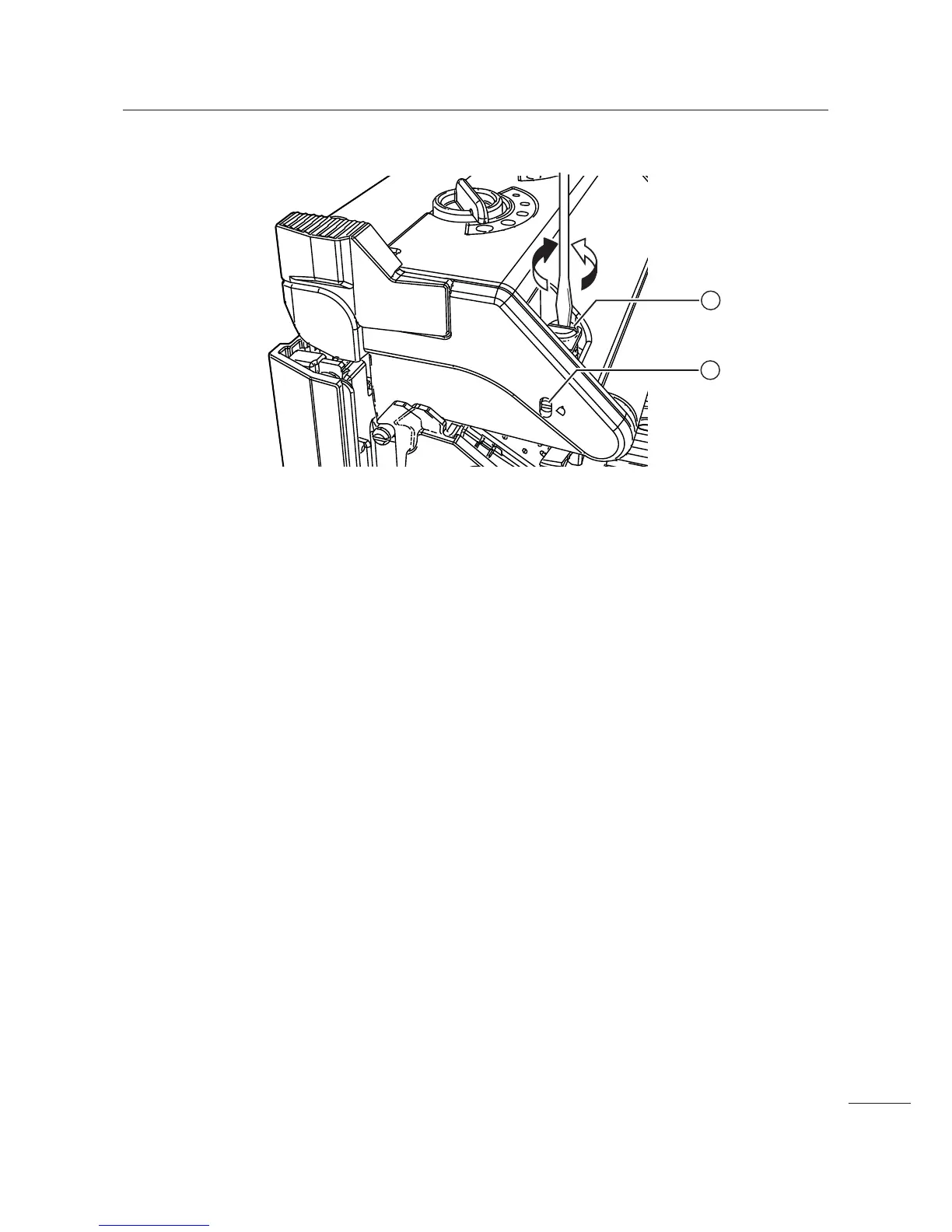
3 Find the head pressure balance adjustment screw 3 on the top of the print head
assembly as shown above.
4 Turn the head pressure balance adjustment screw 3 with a slotted screwdriver.
• Turn the adjustment screw clockwise to increase the pressure on the right side (when you see from
the front of the printer). The indicator
$ on the side of the print head assembly moves downward.
• Turn the adjustment screw counterclockwise to increase the pressure on the left side (when you see
from the front of the printer). The indicator
$ on the side of the print head assembly moves upward.
5 Use media with broad width to perform the factory test print.
Refer to Section 4.4 Test Print Check for details.
6 Check to make sure that the tone of the left and right side of the print image is the
same.
7 If the tone of the left and right side of the print image is not same, repeat the procedure
from steps 4 through 6.
2
3

 Loading...


