.
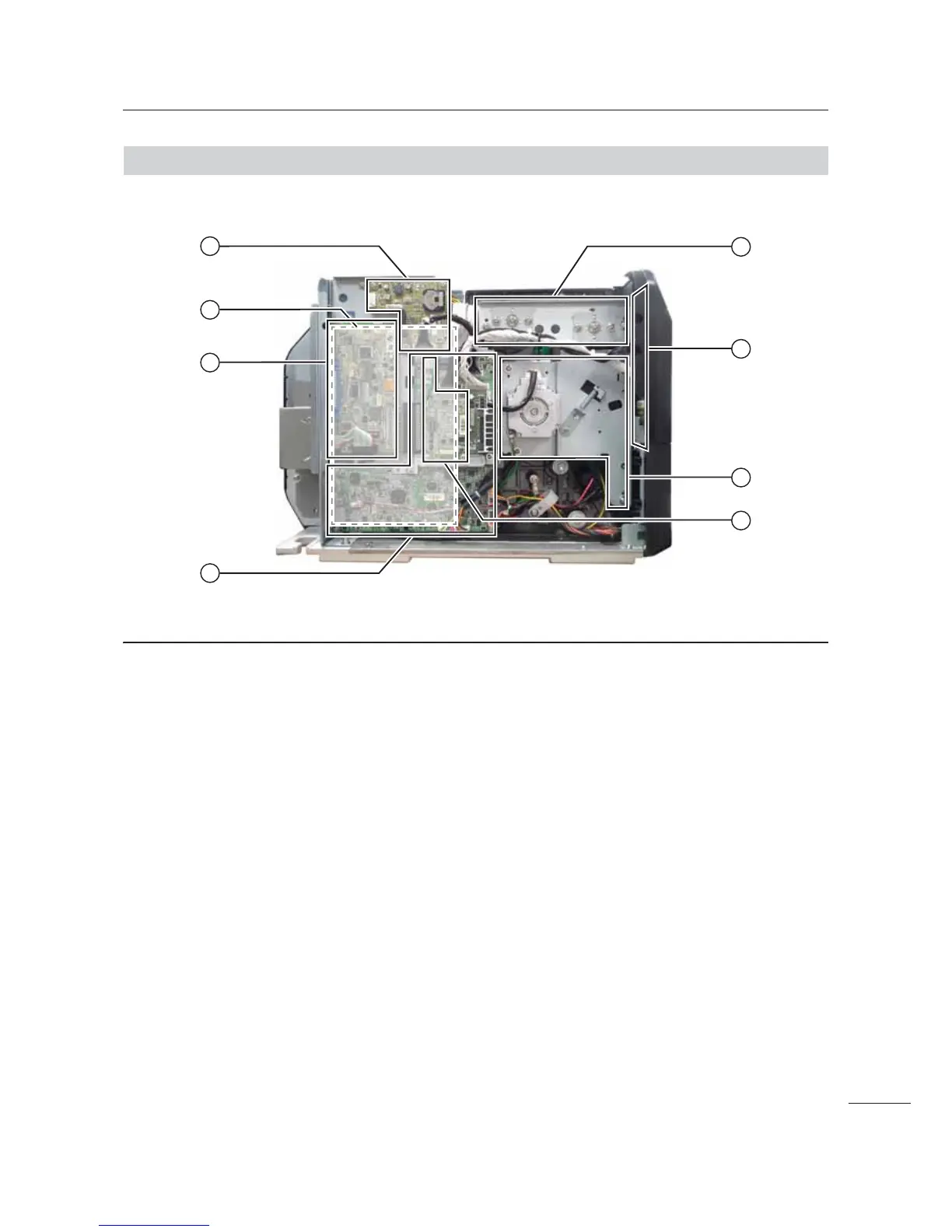
Optional EXT PCB board
The optional EXT PCB is added when
installing the optional RTC (Real Time Clock)
kit, dispenser unit or RFID kit.
3
Power supply unit
This is the power board, which is located
behind the main (CONT) PCB. It contains the
printer’s transformers, relays, etc., for
transference of electrical current from the
supply source to the printer’s control circuits.
$
Interface board
/
Main (CONT) PCB board
The main (CONT) PCB is the primary brain
center for all printer activities.
1
Ribbon frame
To support the ribbon supply spindle and
ribbon rewind spindle.
4
Operator panel (KB) PCB board
This PCB provides the user interaction
functionality via the operational buttons and as
well as the LCD.
2
Gearbox
The stepper motor, timing belt and gears in the
gearbox provide the main rotation motion for
precise print positioning.
(
FPGA PCB board
The FPGA (Field Programmable Gate Array)
board is used as a TPH (Thermal Print Head)
controller. It controls the general of printing
such as print strobe and etc. The main purpose
is for history control of printing.

 Loading...


