5 Replacement
73
CL4NX/CL6NX Service Manual
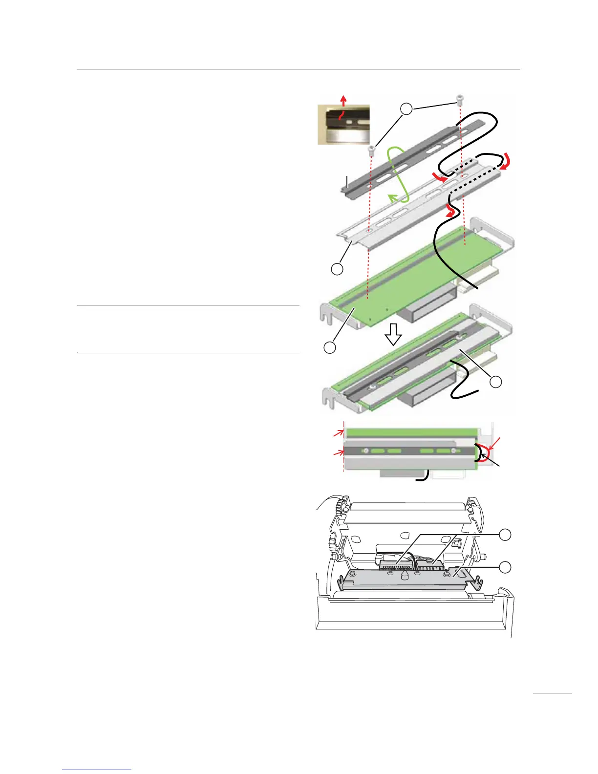
4 Make sure that the UHF (short) antenna
assembly is attached onto the RFID
head cover
4 as shown in the picture.
If not, insert front part of UHF (short) antenna
assembly through the rectangle opening of the
RFID head cover.
Route the antenna wire accordingly.
5 Attach the RFID head cover 4 to the
new print head
, using two screws
(print head)
1.
Align the edge of the RFID head cover 4
carefully to the side of the print head
, as
shown. Then fix the position using the screws.
The print head assembly is known as
RFID print head assembly
" in the later steps.
Note
Make sure that the loop of the antenna wire is as
short as possible.
6 Connect the print head cables to two
connectors
/ of the
RFID print head assembly
".
7 Install the RFID print head assembly ".
Install the print head so that it is locked with a click
sound.
8 Load the media and ribbon back if you
remove them.
After the replacement
• Clear the head counter value.
Refer to Section 4.2 Counter Clear Mode
• Check the print darkness.
Refer to Section 4.5 Adjusting the Print Darkness

 Loading...


