4 Technical Data
18 / 86 EN-US · 30.30.00.00424 · 07 · 10/23
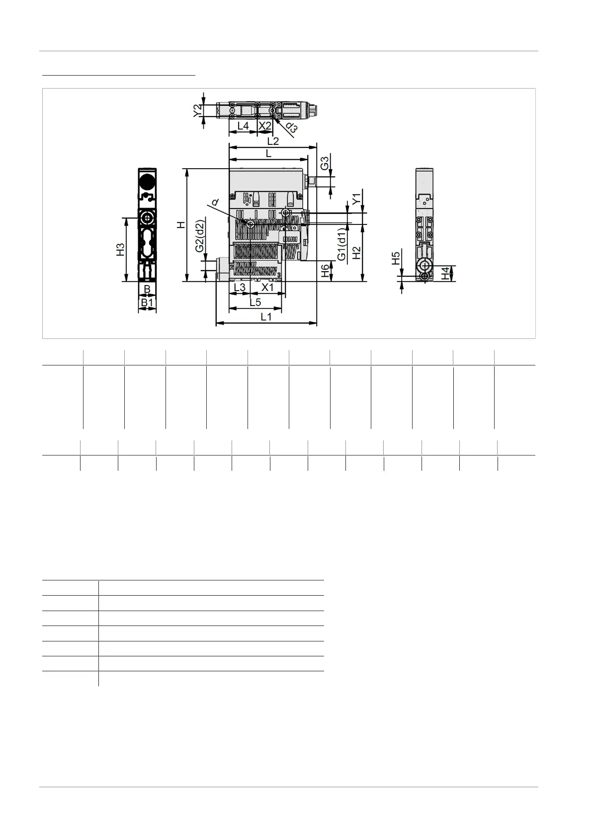
Version with power blow-off (M)
B B1 d
(d1)
1
(d2)
1
d3 G1 G2 G3 H H2 H3
18 18.6 4.4 6 / 8 6 / 8 2.6 1/8"
inter-
nal
threa
d
1/8"
inter-
nal
threa
d
M12x
1 ex-
ternal
threa
d
117.8 59.6 66.35
H4 H5 H6 L L1 L2 L3 L4 L5 X1 X2 Y1 Y2
16.5 5.5 21.8 83.8 105 91.5 22 29.5 54.8 36.9 16 12 12
1)
Depending on the design of the push-in connection.
All specifications are in mm
4.7Pneumatic Circuit Plans
The pneumatic circuit diagrams are shown in simplified form.
Key:
NC Normally closed
NO Normally open
IMP Bistable, pulse-controlled
M Power blow off
1 Compressed air connection
2 Vacuum connection
3 Exhaust outlet