9 Installation
56 / 86 EN-US · 30.30.00.00424 · 07 · 10/23
9.5.1Process Data
Once communication with an IO-Link master has been established, the master begins the automatic cyclic
exchange of process data. The master receives new process output data (PDO) from the controller or field
bus level and passes this on to the ejector for control. The feedback and measured values from the ejector
are collected from the master as process input data (PDI) and forwarded to the system controller. In the
two possible IO-Link revisions 1.1 and 1.0, the process data from the ejector is as follows:
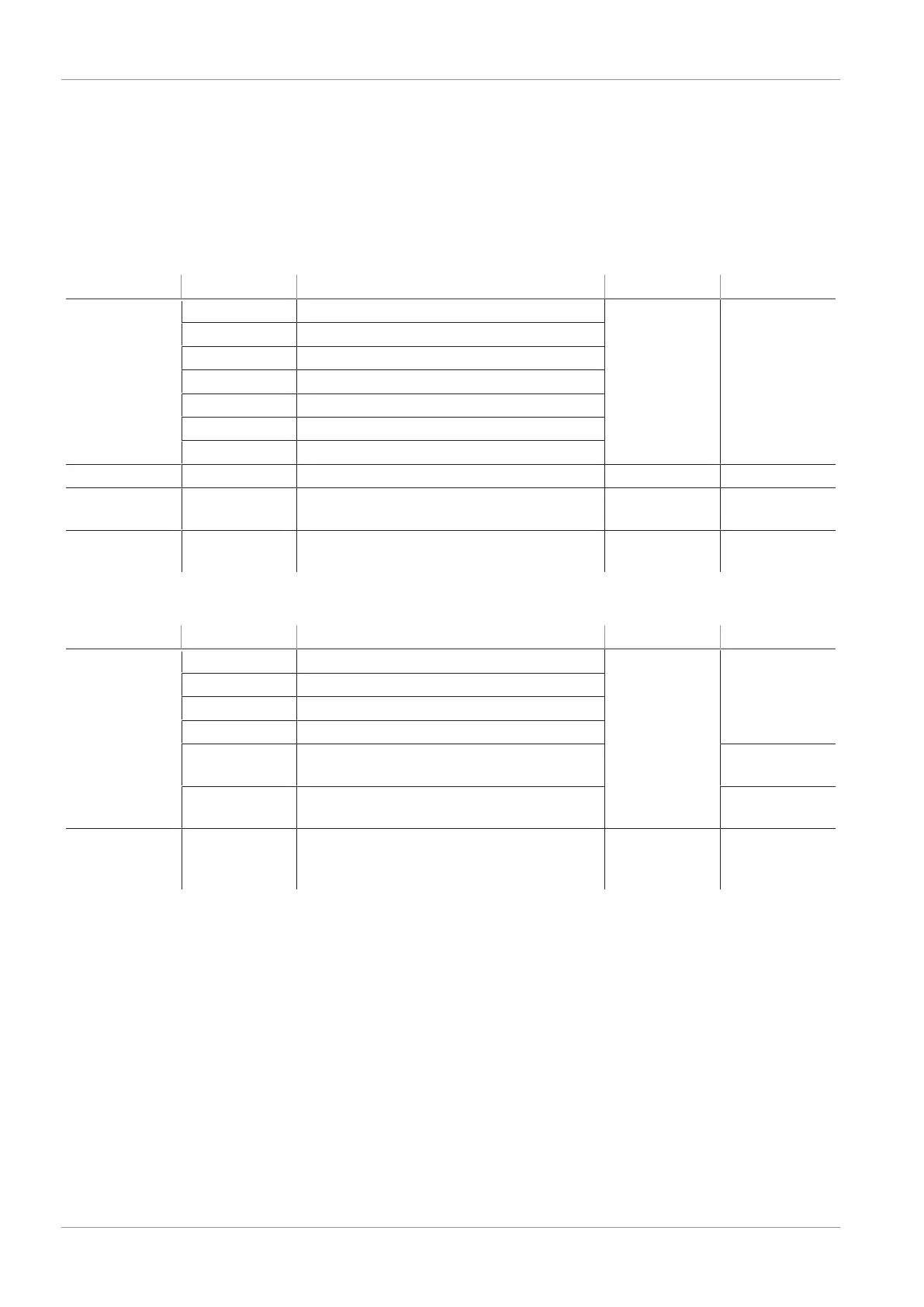
Process Input Data (PDI)
PDI bytes Bit Parameter IO-Link 1.1 IO-Link 1.0
0 0 Part Present (H2) X X
1 Air saving function (H1)
3 CM-Autoset acknowledgment
4 EPC-Select acknowledgment
5 Device status – green
6 Device status – yellow
7 Device status – red
1 7...0 Multifunctional EPC value 1 X -
2 7...0 Multifunctional EPC value 2…..(high-
byte)
X -
3 7...0 Multifunctional EPC value 2…..(low-
byte)
X -
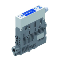
Process Output Data (PDO)
PDI bytes Bit Parameter IO-Link 1.1 IO-Link 1.0
0 0 Vacuum on/off X X
1 Blow off active
2 Setup mode
3 CM Autoset
5...4 EPC-Select: switching the multifunc-
tional EPC values
-
7...6 Switching production setup profiles P0–
P3
X
1 7...0 Inlet pressure in 0.1bar (measured
value from external pressure sensor, 0 =
function inactive)
X -
9.6Start of Operations
A typical handling cycle is divided into the following three phases:
• Phase 1: Suction, switching steps 1 and 2
• Phase 2: Deposit, switching steps 3 and 4
• Phase 3: Idle state, switching steps 5 and 6
To check whether sufficient vacuum has built up, the limit value H2 is monitored by an integrated vacuum
sensor during suction and output to the higher-level controller via OUT.