9 Installation
52 / 86 EN-US · 30.30.00.00424 · 07 · 10/23
9.4Electrical connection
WARNING
Electric shock
Risk of injury
4 Operate the product using a power supply unit with protected extra-low voltage
(PELV).
WARNING
By activating/deactivating the product, output signals lead to an action in the pro-
duction process!
Personal injury
4 Avoid possible danger zone.
4 Remain vigilant.
NOTE
Incorrect power supply
Destruction of the integrated electronics
4 Operate the product using a power supply unit with protected extra-low voltage
(PELV).
4 The system must incorporate safe electrical cut-off of the power supply in compliance
with EN60204.
4 Do not connect or disconnect the connector under tension and/or when voltage is ap-
plied.
NOTE
Power load too high
Destruction of the vacuum switch, as there is no protection against overloading!
4 Prevent constant load currents > 0.1A.
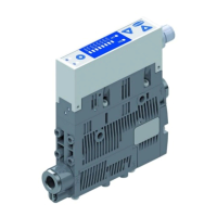
The electrical connection is established using a 5-pin M12 connector that supplies the device with voltage,
and contains the two input signals and the output signal. The inputs and outputs are not electrically iso-
lated from one another.
The maximum line length for the supply voltage, the signal inputs and the signal output is:
• 30m in SIO mode
• 20m in IO-Link mode
Establish the ejector’s electrical connection using plug connector 1 as shown in the figure.