9 Installation
EN-US · 30.30.00.00424 · 07 · 10/23 51 / 86
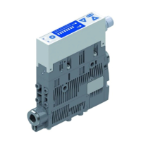
The compressed air connection G1/8" is marked with the number 1 on the ejector.
4 Connect compressed air hose. The max. tightening torque is 3Nm.
The 1/8" vacuum connection is marked with the number 2 on the ejector.
4 Connect the vacuum hose. The max. tightening torque is 3Nm.
9.3.2Instructions for the Pneumatic Connection
Use only screw unions with cylindrical G-threads for the compressed air and vacuum connection!
To ensure problem-free operation and a long service life for the product, only use adequately maintained
compressed air and take the following requirements into account:
• Use of air or neutral gas in accordance with EN 983, filtered 5 μm, oiled or
unoiled.
• Dirt particles or foreign bodies in the product connections, hoses or pipe-
lines can lead to partial or complete malfunction.
1. Shorten the hoses and pipelines as much as possible.
2. Keep hose lines free of bends and crimps.
3. Only use a hose or pipe with the recommended internal diameter to connect the product; otherwise,
use the next largest diameter.
- On the compressed air side, ensure that the internal diameter has the dimensions required for the
product to achieve its performance data.
- On the vacuum side, ensure that the internal diameters have the necessary dimensions for prevent-
ing high flow resistance. If the selected internal diameter is too small, the flow restrictor and the
evacuation times increase and the blow off times are extended.
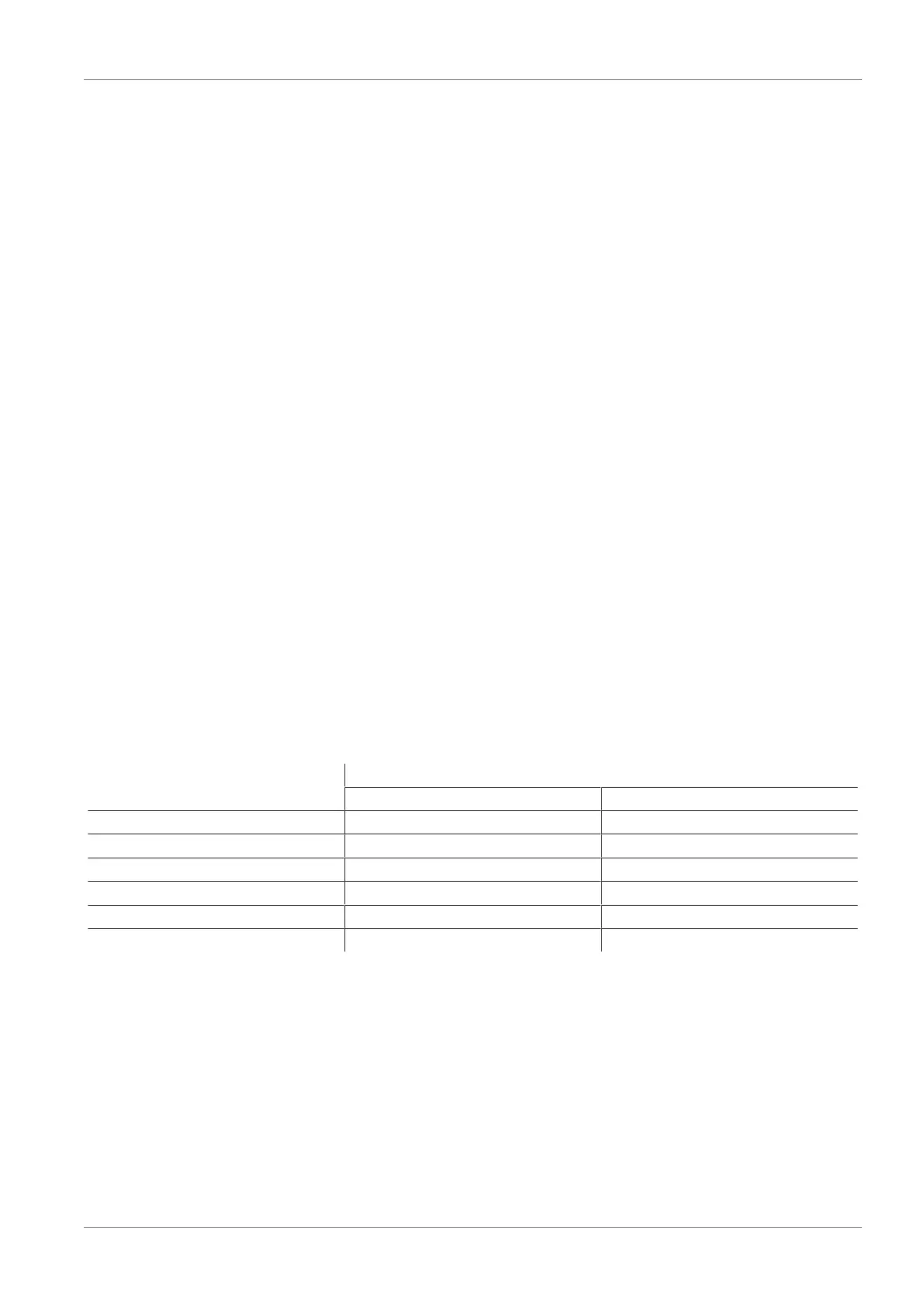
The following table shows the recommended line cross-sections (internal diameter):
Performance class Line cross-section (internal diameter) in mm
1)
Pressure side Vacuum side
07 4 4
10 4 4
15 4 6
2-07 4 4
2-09 4 4
2-14 4 6
1)
Based on a maximum hose length of 2m.
4 For longer hose lengths, the cross-sections must also be larger.