6-8 Installation Date Code 20011026
SEL-321/321-1 Instruction Manual
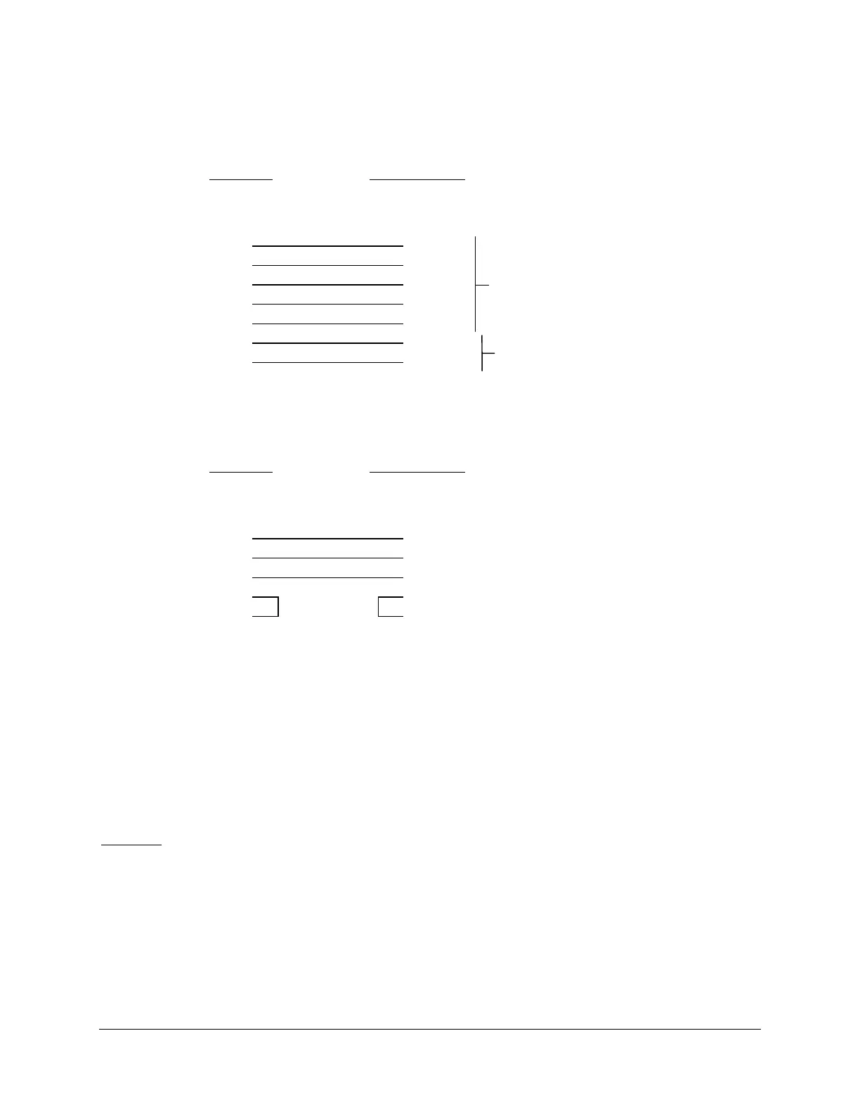
3 TXD
2 RXD
5 GND
8 CTS
7 RTS
2 +IRIG
3 -IRIG
Cable 239
Data and IRIG-B
SEL-2020
9-Pin Male
“D” Subconnector
SEL-321 Relay
9-Pin Male
“D” Subconnector
Cable 272A
Data Only
SEL-2020
9-Pin Male
“D” Subconnector
SEL-321 Relay
9-Pin Male
“D” Subconnector
* DTE = Data Terminal Equipment (Computer, Terminal, Printer, etc.)
** DCE = Data Communications Equipment (Modem, etc.)
COMMUNICATIONS
This subsection describes how you can optimize the communications interface between the
SEL-321 Relay and other devices it will communicate with.
Modems
If electrical interference is a problem, consider using point-to-point fiber-optic modems to
provide electrical isolation and noise immunity. We recommend the SEL-2800/2810 Fiber-Optic
Transceivers for these applications. The connection between the SEL-321 Relay and the modem
is EIA-232. The connection between the remote modem and the remote device is also EIA-232.
Optical fibers connect the two modems.
For sites where the main issue is cable length, you can use short-haul modems connected by wire.
This alternative is a compromise between the low cost and short cable for direct EIA-232
connections and the isolation and noise immunity of higher-cost fiber-optic links.
RXD 2
TXD 3
GND 5
RTS 7
CTS 8
+IRIG 4
-IRIG 6
RXD 2
TXD 3
GND 5
RTS 7
CTS 8
3 TXD
2 RXD
5 GND
8 CTS
7 RTS
Rear-Panel Port
Demodulated IRIG-B Port