Date Code 20011026 Specifications 2-45
SEL-321/321-1 Instruction Manual
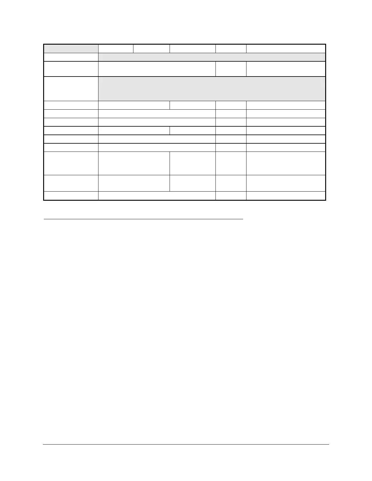
Port 1 Port 2 Port 3 IRIG-B Comment
Description
Type EIA-232 Time
Code
Connector
Pin
Assignments
1 +5 Vdc N/C +5 Vdc N/C = No connection
2 RXD +IRIG-B RXD = Receive data input
3 TXD -IRIG-B TXD = Transmit data output
4 +12 Vdc N/C N/C +12 Vdc @ 4 mA (max)
5 GND GND Signal Ground
6 N/C N/C No connection
7 RTS RTS
always asserted
N/C RTS = Data buffer full when
asserted
Port 3 always asserted
8 CTS N/C N/C N/C = No connection
CTS = Transmit if asserted
9 GND GND Signal ground
Internal Time Clock Time-Code Synchronization Specifications
The relay internal time clock is the time reference for all relay functions. Connect the rear panel
port marked DEMODULATED IRIG-B to synchronize to an external time source.
Without an external IRIG-B time-code source, the internal time clock drift rate is ±0.086
sec./day. With IRIG-B, the internal clock is synchronized to within ±1 ms of the time source.
Note that without an external IRIG-B time-code source, the date and time must be set whenever
the relay power is cycled. See Section 6: Installation for further information.
SELF-TESTS
The relay runs a variety of self-tests. Table 2.29 summarizes the tests and their outputs and
parameters. Some tests have warning and failure states, others only failure states. The relay
generates a status report after any change in self-test status. This report may be retrieved using
the STATUS command. Table 2.29 shows relay actions for any self-test condition: warning (W)
or failure (F).