Date Code 20011026 Specifications 2-1
SEL-321/321-1 Instruction Manual
SECTION 2: SPECIFICATIONS
OVERVIEW
The relay contains protection elements, many logic schemes, programmable I/O and logic, event
recording, fault locating, metering, and other functions.
Outputs from all of the protection elements, logic schemes, etc., are available to the program-
mable logic (SEL
OGIC
®
control equations) for tripping, alarming, keying communications, and
any other desired functions.
The relay includes three serial communications ports and a front-panel user interface for entering
settings, reviewing operations, checking metering, and other functions.
SETTING STRUCTURE
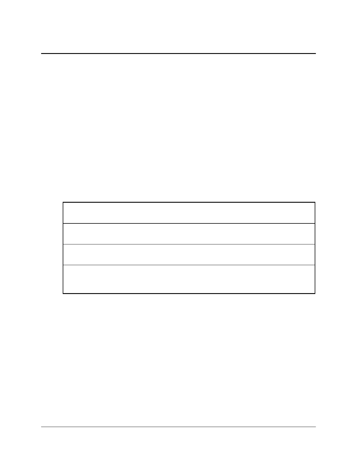
The relay has four types of settings, as shown in Table 2.1.
Table 2.1: Relay Setting Structure
Communications Port Settings (SET P command)
Assign the parameters of the three EIA-232 ports
Global Settings (SET G command)
Assign contact inputs, LCD illumination timeout, and setting group switch delay
Logic Settings (SET L command)
Program tripping functions and output contacts using SEL
OGIC control equations
All Remaining Settings (SET command)
Select and set protective element boundaries and thresholds, communications assisted
trip and other schemes
The setting procedure has enables for each group of features and characteristics. If you do not
select a feature (e.g., out-of-step protection), the relay does not prompt you for those settings.
The following information is set using the SET command for each of the six setting groups.
LINE AND RELAY TERMINAL INFORMATION
The relay accepts information which describes the line section in terms of positive- and zero-
sequence secondary impedances. The fault location algorithm uses these replica impedances
directly. The distance elements use the positive-sequence impedance angle for calculations.