6-10 Installation Date Code 20011026
SEL-321/321-1 Instruction Manual
You can set your own passwords with the PASSWORD command (see Section 3:
Communications), or you can disable the password protection with jumper selection (see Main
Board Jumpers below).
JUMPER SETTINGS
This subsection describes the hardware jumper selections available on the SEL-321 Relay, and
the recommended procedures for making the jumper setting changes.
Main Board Jumpers
Set the main board jumpers to meet your requirements. See Table 6.1 for jumper functions and
positions. See Appendix B for jumper locations on the main board.
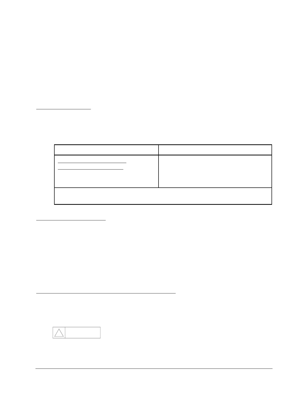
Table 6.1: Main Board Jumper Positions
Function Install Jumpers At:
Password Protection Disabled
Password Protection Enabled
(default)
P7: J105 shorting block installed
P7: J105 shorting block removed
OPEN/CLOSE Command Enable (default)
OPEN/CLOSE Command Disable
P7: J106 shorting block installed
P7: J106 shorting block removed
Note: Unused (spare) jumpers may be placed on P7 locations labeled “GND.” P7: J101
through P7: J204 do not provide any function.
Input/Output Connections
Your SEL-321 Relay is equipped with one or two input/output (I/O) boards.
Configure the Output Contact Form
The SEL-321 Relay I/O boards are shipped from the factory with form A output contacts (except
for the alarm contact). You may reconfigure the contacts by desoldering and then resoldering the
20 AWG jumper wire for each contact. See Appendix I for information on jumper locations and
positions required to configure the contacts.
Open the SEL-321 Relay to Access Internal Jumpers
If you have decided that the SEL-321 Relay default configuration does not meet your needs,
perform the following steps to gain access to internal jumpers:
1. De-energize the SEL-321 Relay.
CAUTION
!
Never work on the relay with the front or top cover removed, when the
relay is energized.