7-6 Maintenance and Testing Date Code 20011026
SEL-321/321-1 Instruction Manual
Energize the IN1 input for the duration of this step to block the Switch-Onto-
Fault logic from operating. If dc voltage source is not available, set ESOTF
= N in the relay settings.
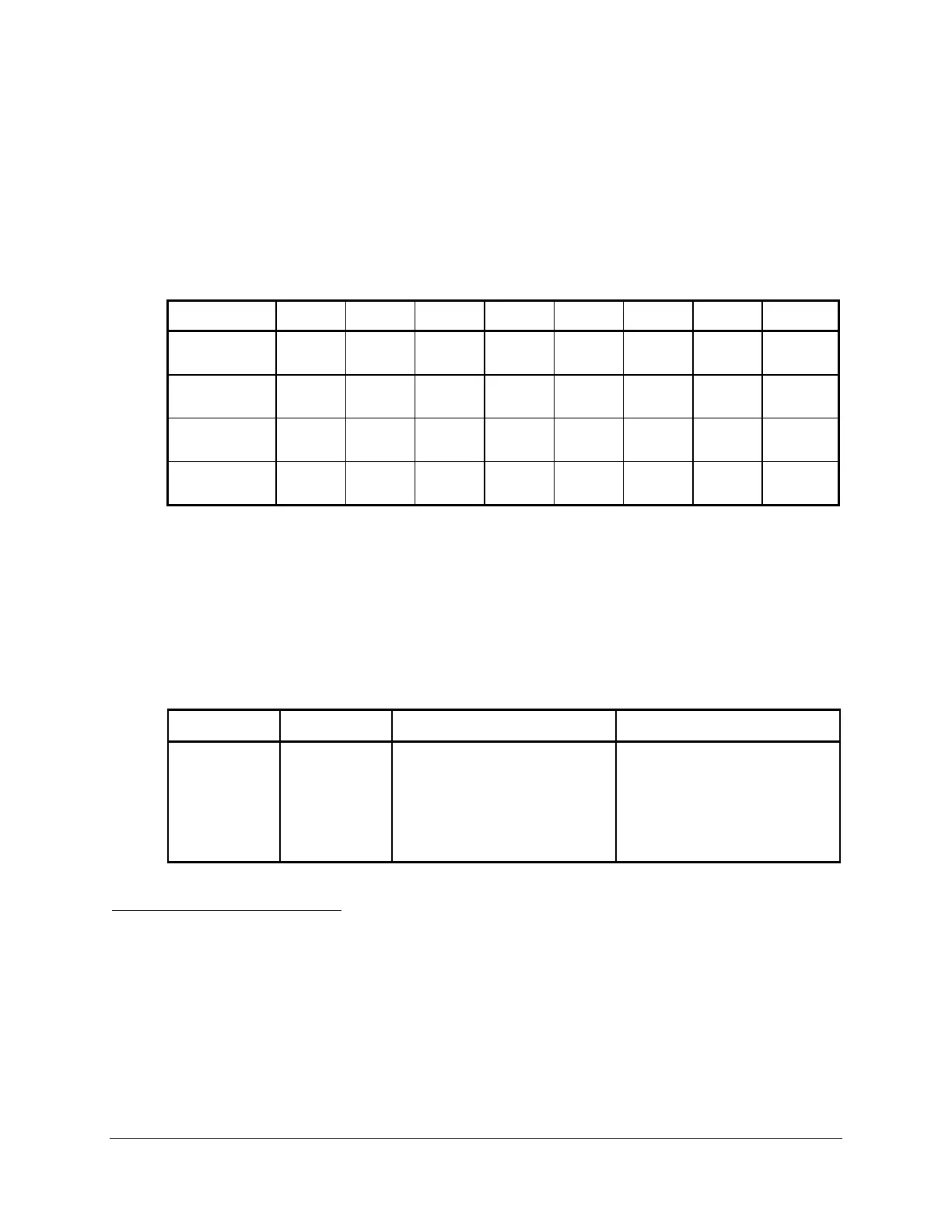
Run ground fault tests using the test source connections shown in Figure 7.3, Figure
7.4, or Figure 7.6. Run phase-to-phase fault tests using the test source connections
shown in Figure 7.2, Figure 7.4, or Figure 7.7.
Table 7.1: Fault Locator Test Values
Location Type VA VB VC IA IB IC Units
75 miles AG 52.89
0.00
69.97
-124.30
70.34
124.10
5.24
-82.40
0.00
0.00
0.00
0.00
V or A
Degrees
BC 67.00
0.00
56.75
-126.20
56.75
126.20
0.00
0.00
7.83
-174.00
7.83
6.00
V or A
Degrees
85 miles AG 54.24
0.00
69.67
-123.90
70.00
123.70
4.74
-82.40
0.00
0.00
0.00
0.00
V or A
Degrees
BC 67.00
0.00
57.69
-125.50
57.69
125.50
0.00
0.00
7.08
-174.00
7.08
6.00
V or A
Degrees
Faults at 75 miles are within Zone 1, since the Zone 1 reach setting is 80% of the 100-mile line
positive-sequence impedance (see Z1P, Z1MG, and XG1 in the settings). Faults at 85 miles are
beyond Zone 1, but within Zone 2.
Faults listed in Table 7.1 cause certain combinations of output contacts to close and front panel
LEDs to illuminate. You may use the front panel LCD functions to examine the short form fault
data following each test. Table 7.2 shows the expected results.
Table 7.2: Output Contact and Target LED Results
Location Type Output Relays Target LEDs
75 miles AG OUT1, OUT2, OUT4 INST, Zone 1, A, G
75 miles BC OUT1, OUT2, OUT4 INST, Zone 1, B, C
85 miles AG OUT1, OUT2, OUT4 TIME, Zone 2, A, G
85 miles BC OUT1, OUT2, OUT4 TIME, Zone 2, B, C
Output Contact Explanation
The OUT1 and OUT2 are set to close for three-pole trips. The relay is set to trip instantaneously
for Zone 1 faults, with a short time delay for Zone 2 faults, and by operation of the residual and
negative-sequence time-overcurrent elements. OUT4 is set to close for assertion of the KEY
element. The KEY element is used in Permissive Overreaching Transfer Tripping protection
schemes to send the permissive signal to the remote end. The SEL-321 Relay asserts the KEY
element when overreaching Zone 2 elements pick up, if other conditions permit.