Date Code 20011026 Specifications 2-41
SEL-321/321-1 Instruction Manual
Table 2.26: Fault Location Triggering Elements
Fault Type Elements Which Must be Asserted
Phase-to-Phase Faults
Three-Phase Faults
Phase-to-Phase-Ground Faults
Line-Ground Faults
M1P - M4P
M1P - M4P
M1P - M4P
Z1G - Z4G, 67N1 - 67N4, 51NP
Fault locations are calculated from the data in the longest contiguous sequence of rows where at
least one of the elements in Table 2.26 is asserted.
If the longest contiguous sequence duration is less than one-half cycle, a single-pole open
condition is detected (SPO is asserted), or if none of the elements in Table 2.26 assert, the relay
does not calculate a fault location. For these cases, $$$$$$ is reported for a fault location.
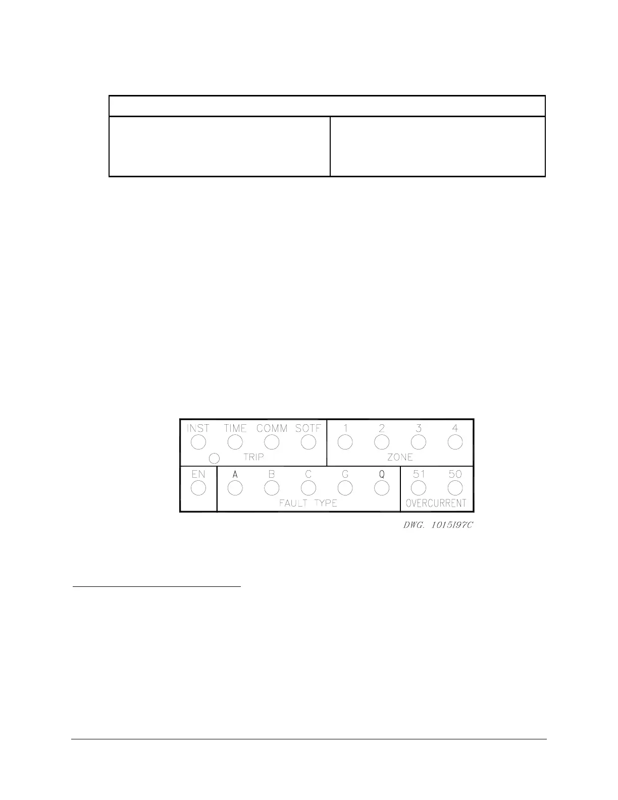
FRONT-PANEL TARGETS
The relay presents targets by two means:
• A two row, 16 column back lighted LCD display
• Two rows of eight target/indicator LEDs
The LCD display shows the detailed information pertaining to a fault detected by the relay,
displaying metering information, relay self-test status information, etc. The LEDs designations
are shown in Figure 2.3.
Figure 2.3: SEL-321 Front-Panel Targeting
General Target LED Description
Under normal operating conditions, only the enable (EN) LED is illuminated. Other LEDs
illuminate when the relay trips. These LEDs are latching until reset by pressing the Target Reset
Button, executing the Target R command, or removing power from the relay.
When a new trip occurs, the targets clear and display the latest tripping target.
Only elements masked for tripping illuminate the front-panel target LEDs for a tripping event;
unused elements do not target. Refer to the following list of target illumination conditions for
the rising edge of TPA, TPB, TPC, or 3PT.