I-2 Interface Board Specifications Date Code 20011026
SEL-321/321-1 Instruction Manual
Output Contacts
30 A make
6 A carry
Not rated for interrupting duty
Closing (pickup for “a” contacts, dropout for “b” contacts): 1/4-cycle or less
Opening (dropout for “a” contacts, pickup for “b” contacts): 1/2-cycle or less (typical is
1/4-cycle)
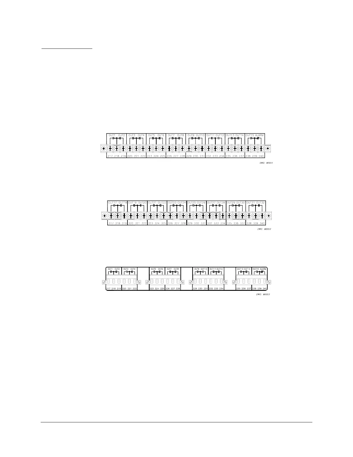
Interface board 1 provides 16 contact outputs. These 16 standard dry output contacts share a
common terminal for each pair of contacts, but are not polarity dependent. The rear of the relay
will be similar to the following figures:
Figure I.1: Interface Board 1 Output Contacts (Board Position 1)
Figure I.2: Interface Board 1 Output Contacts (Board Position 2)
Figure I.3: Interface Board 1 Output Contacts (Board Position 1) (Plug-In Connections)
Configure the output contacts as “a” contacts or “b” contacts with solder jumpers. Figure I.4 and
Figure I.5 show the locations of the jumpers and explain the jumper positions. Contacts are
factory-configured as “a” contacts (except the alarm contact which is “b”).