I-6 Interface Board Specifications Date Code 20011026
SEL-321/321-1 Instruction Manual
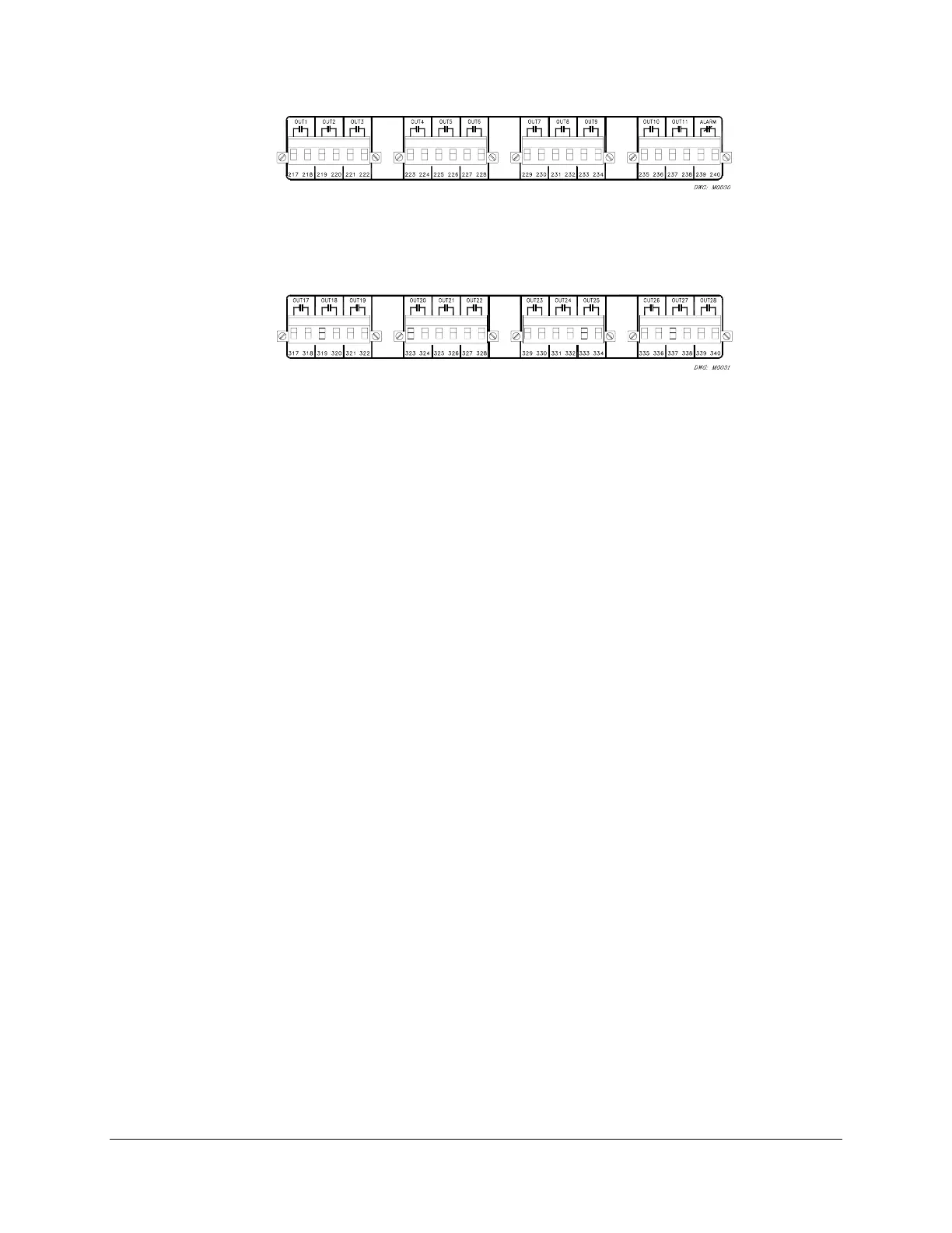
Figure I.8: Interface Board 2 Output Contacts (Board Position 1) (Plug-In Connections)
Figure I.9: Interface Board 2 Output Contacts (Board Position 2) (Plug-In Connections)
Configure the output contacts as “a” contacts or “b” contacts with solder jumpers. Figure I.10
and Figure I.11 show the locations of the jumpers and explain the jumper positions. Contacts are
factory-configured as “a” contacts (except the alarm contact which is “b”).