13
INSTALLATION AND MAINTENANCE
LSA 42.2 - 2 & 4 POLE
ALTERNATORS
3433 en - 2010.10 / g
LEROY-SOMER
4.6 - Dismantling, reassembly (see sections
5.4.1. & 5.4.2)
During the warranty period, this operation must only
be carried out in an approved workshop or in our
factory, otherwise the warranty may be invalidated.
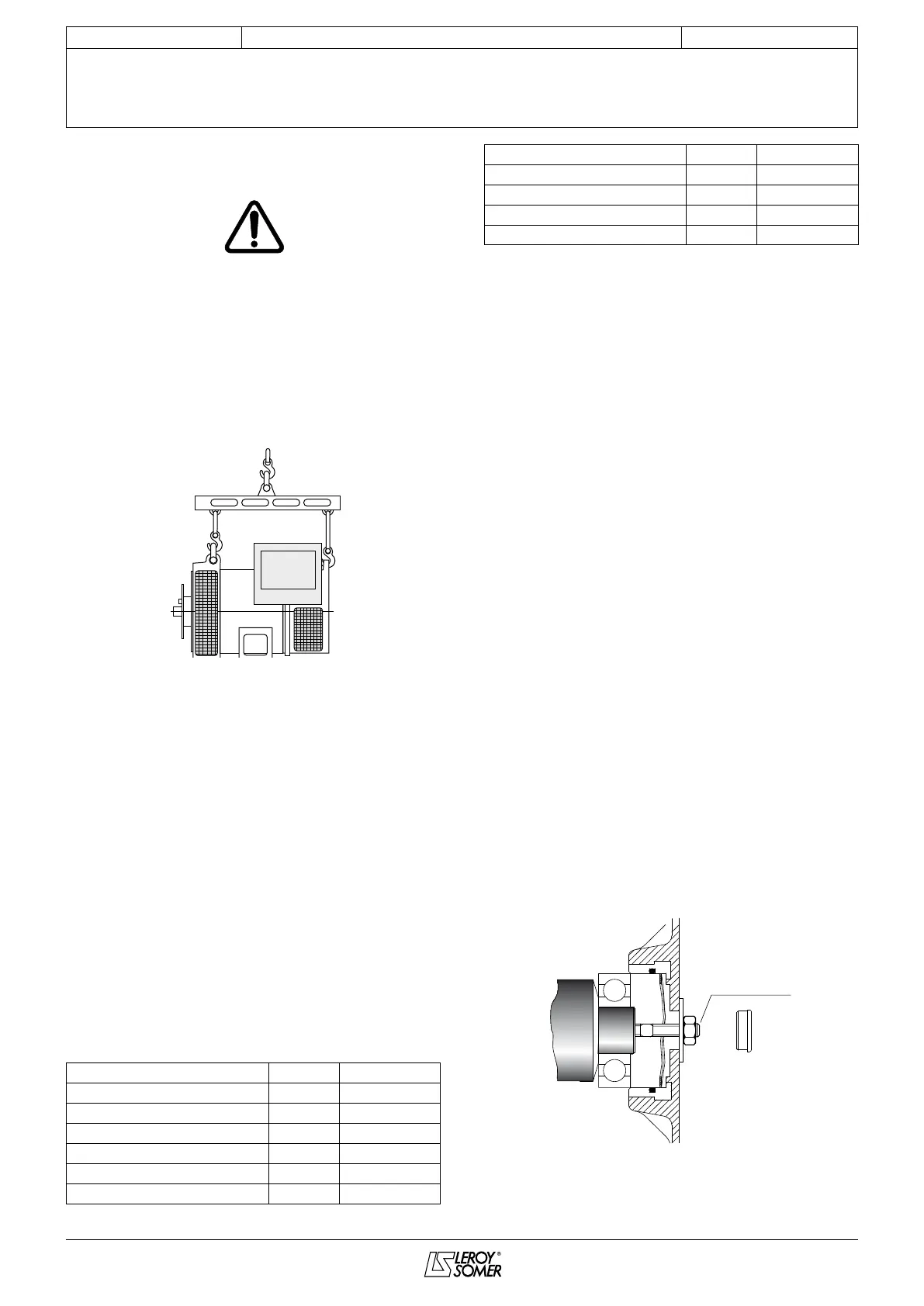
Whilst being handled, the alternator must remain
horizontal (rotor not locked when moved). Check
how much the alternator weighs (see 4.7) before
choosing the lifting method.
The choice of lifting hooks or handles should be
determined by the shape of the lifting rings.
4.6.1 - Tools required
To fully dismantle the alternator, we recommend using the
tools listed below:
- 1 ratchet spanner + extension
- 1 torque wrench
- 1 7 mm at spanner
- 1 8 mm at spanner
- 1 10 mm at spanner
- 1 12 mm at spanner
- 1 8 mm socket
- 1 10 mm socket
- 1 13 mm socket
- 1 5 mm Allen key (eg. Facom: ET5)
- 1 6 mm Allen key (eg. Facom: ET6)
- 1 TORX T20 bit
- 1 TORX T30 bit
- 1 puller (eg. Facom: U35)
- 1 puller (eg. Facom: U32/350).
4.6.2 - Screw tightening torque
IDENTIFICATION screw Ø Torque N.m
Field term. block screw M4 4 N.m
Field screw M6 10 N.m
Diode bridge screw M 6 5 N.m
Diode nut M 5 4 N.m
Assembly rod M 8 20 N.m
Earth screw M 6 5 N.m
Balancing bolt M 5 4 N.m
Discs/shaft screw M 10 66 N.m
Lifting screw M 8 4 N.m
Grille screw M 6 5 N.m
Cover screw M 6 5 N.m
4.6.3 - Access to connections and the regulation
system
The terminals are accessed by removing the terminal box lid
[48].
To access the adjustment potentiometers on the AVR, the side
plate should be removed [367].
4.6.4 - Accessing, checking and replacing
diodes
4.6.4.1 - Dismantling
- Remove the terminal box lid [48].
- Remove the air intake louvre [51].
- Unscrew the xing clamps on the power output cables,
disconnect E+, E- on the exciter and R 791 module.
- Remove the 4 nuts on the tie rods.
- Remove the NDE bracket [36] using an extractor: eg. U.32 -
350 (FACOM).
- Remove the surge suppressor [347].
- Remove the 4 xing screws from the diode bridges on the
armature.
- Disconnect the diodes.
- Check the 6 diodes using either an ohmmeter or a battery
lamp (see section 4.5.1).
4.6.4.2 - Reassembly
- Replace the diodes, respecting the polarity (see section
4.5.1).
- Replace the surge suppressor [347].
- Insert a new O ring in the bearing housing.
- Ret the NDE bracket and pass the bundle of wires between
the top bars of the ange.
- Replace the xing clamps on the cables and the R 791
module.
- Ret the air intake louvre [51].
- Replace the terminal box lid [48].
Rotor
NDE bracket
M8
Threaded bar