Section 04 ENGINE (2-STROKE)
Subsection 07 (EXHAUST SYSTEM)
Expansion Pipe and Muffler
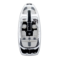
Apply Loctite 592 on threads of fittings no. 11.
Tighten fittings to 5 N•m(44lbf•in) then position
as per following illustration. Do not screw more
than 1 turn while positioning. Do not unscrew to
reposition.
F22D0IA
90° 90°
F22D0JA
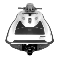
30°
Pressurize the wall jacket to 103 kPa (15 PSI)
through the fittings. No leak should occur.
Position muffler no. 15 in its location. Do not in-
stall the strap and the small clamp yet.
Insert expansion pipe in its position.
WARNING
Pay attention not to bend injection oil cable
or throttle cable.
Loosely install a NEW clamp no. 2.
CAUTION: Those clamp type are not designed
to be removed and reinstalled many times. Re-
installing a used clamp is likely to fail.
Reinstall hoses to T-fittings no. 11. Rear hoses
can be connected on any fitting. Ensure to keep
the same hose routing (inverted U shape).
CAUTION: If hoses length or routing were
changed, water ingestion might occur when
watercraft tips over.
Strongly push expansion pipe toward muffler to
insert it into bellow no. 16.
smr2004-3D 19
 Loading...