Section 04 ENGINE (2-STROKE)
Subsection 07 (EXHAUST SYSTEM)
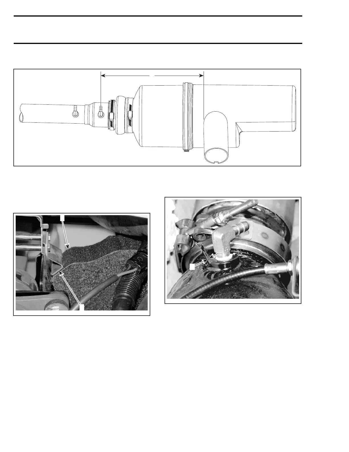
To ensure pipe end is well inserted in muffler, measure the distance as shown in the following illustration.
F22D0KS
A
A.322mm(12.68in)
Insert foam under expansion pipe. Ensure foam
is not against muffler bellow.
Position foam under bracket edge so that it is prop-
erly retained.
F22D0LA
2
1
1. Bracket edge
2. Foam
Rotate expansion pipe to position its T-fittings ver-
tically.
CAUTION: If T-fittings were not installed verti-
cally, water ingestion might occur when water-
craft tips over.
Tighten front clamp no. 2 as follows.
– Ensure to align expansion pipe with tuned pipe
so that their ends are in contact all around.
– Tighten clamp while maintaining expansion pipe
and tuned pipe together.
– Torqueclampto11N•m(97lbf•in).
– Ensure there is a gap between clamp ends.
Otherwise, try another clamp.
F22D0MA
A
A. Clamp ends must have a gap here
Ensure there is a gap between hose at front T-fit-
ting and fuel tank.
20 smr2004-3D
 Loading...