Section 14 STEERING SYSTEM
Subsection 01 (STEERING SYSTEM)
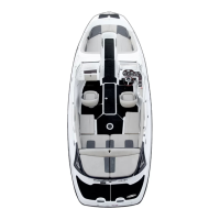
Snap cover of steering padding support no. 16 on
screw heads.
F22K21A
Ensure handlebar adjuster works adequately.
Secure steering cable ball joint no. 28 to stem arm
lever.
CAUTION: Ensure the ball joint is parallel to the
stem arm within ±10°.
Properly install remaining components.
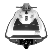
Handle Grip and Grip Insert
When installing the grip insert no. 42 in the han-
dlebar no. 10, ensure that it is properly inserted in
the slot at the end of the handlebar tubing.
F02K0JA
1
TYPICAL
1. Grip insert
Install grip no. 7 on handlebar no. 10 matching it
to the notch in the handlebar.
Install flat washer and screw no. 9.
Torque screw to 7 N•m(62lbf•in).
Install cap no. 8.
F02K0KA
1
2
4
53
TYPICAL
1. Grip insert
2. Grip
3. Flat washer
4. Screw. Torque to 7 N•m (62 lbf•
in)
5. Cap
CAUTION: Ensure to install flat washer other-
wise screw will damage grip end.
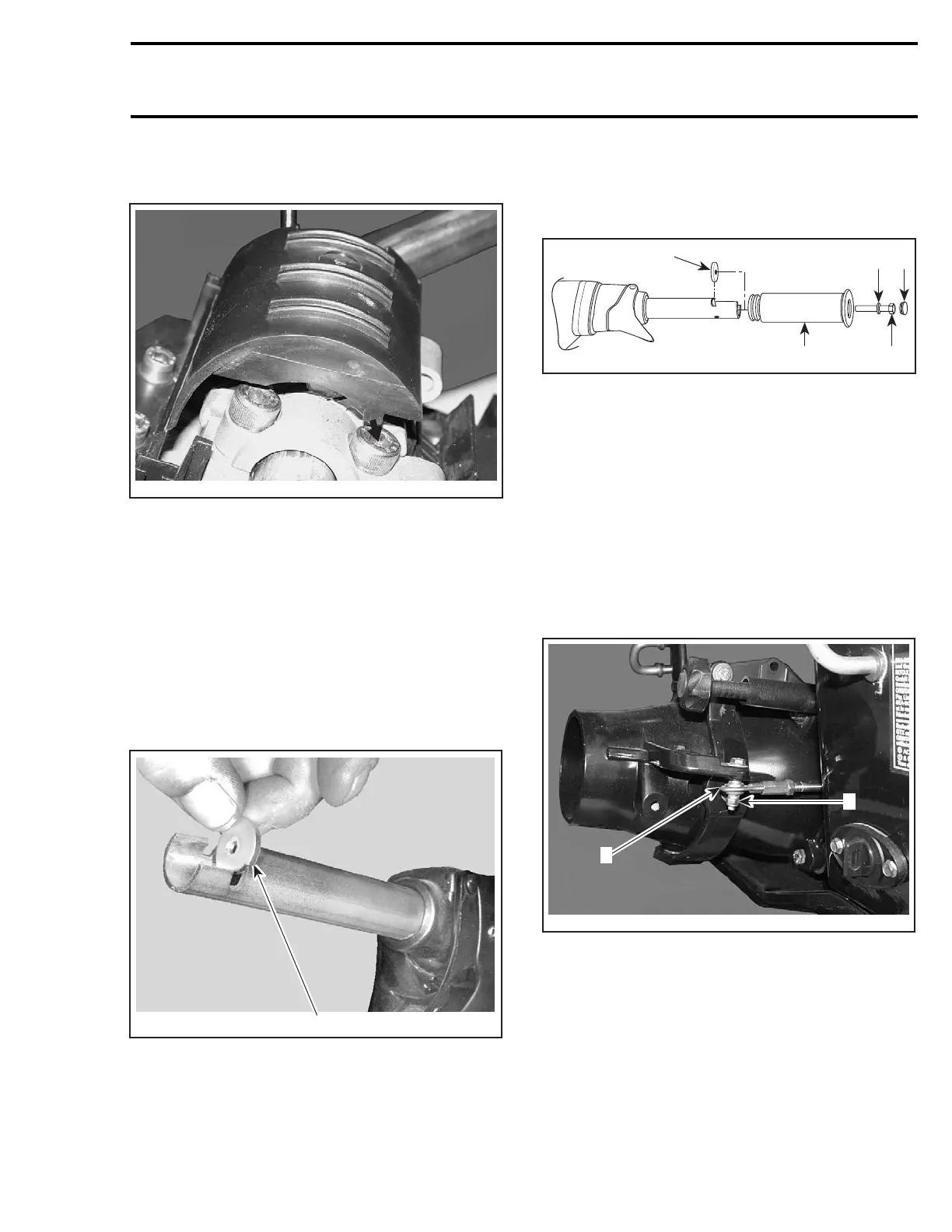
Ball Joint
Secure the steering cable ball joint no. 27 to the
nozzle as per following illustration.
CAUTION: Ensure the ball joint is parallel to the
nozzle arm within ±10°.
F22K24A
1
2
1. Ball joint below steering arm
2. Torque nut to 7 N•m(62lbf•
in)
smr2004-3D 77
 Loading...