“●”: It indicates that specified code parameters cannot be changed or modified while the drive is running.
For ease of programming, the settings have been classified into basic and advanced as mentioned in the
table below.
“○”: It indicates that the specified parameter can be varied irrespective of the drive’s run-state
“×”: It indicates that code parameters are read-only, which cannot be changed or modified.
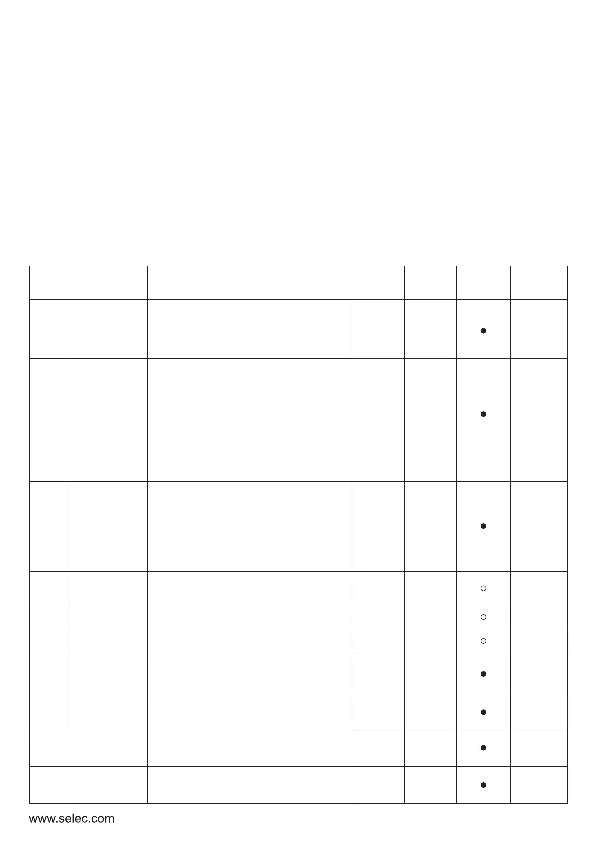
6. SPECIFICATIONS OF FUNCTIONAL PARAMETERS
6-1 Functional Parameters Table
16
User Manual
P0- BASIC FUNCTIONAL PARAMETERS
Fun.
Code
Descrip-
tion
Settings and Range
Default
Value
Basic
Setting
Modifi-
cation
M-bus
Address
P0-00
Parameter
Setting
Mode
0: Display Only Basic Parameters
1: Display All Settable Parameters
2: Disable Parameter Settings
3: Factory Reset
0
Yes
40000
P0-01
Frequency
setting
mode
1
Yes
40001
P0-02
Control
mode for
running
0
Yes
40002
P0-03
Frequency
setting
Lower limiting Frequency (P0-10)-
Upper limiting Frequency (P0-09)
50.0 Hz
Yes
40003
P0-04 Acc. time 0 0.1s – 999.9 s 10.0 s
Yes
40004
P0-05 Dec. time 0 0.1s – 999.9 s 10.0 s
Yes
40005
P0-06
Default
running
direction
0: Default direction
1: Reverse direction
0
Yes
40006
P0-07
Anti-reversion
setting
0: Disable, 1: Enable
0
Yes
40007
P0-08
Max.
Frequency
Upper Limiting Frequency (P0-09)
- 400 Hz
60.0 Hz
Yes
40008
P0-09
Upper limiting
frequency
Lower Limiting Frequency (P0-10) -
maximum Frequency (P0-08)
50.0 Hz
Yes
40009
0: Frequency Setting-UP/DOWN Key
1: Panel Potentiometer
2: External AI1Current; 3: External AI2 Volt
4. External AI2 POT; 5: PI Regulation
6: Terminal setting Step Size
7: Terminal Setting step size with 0
Zero frequency after stop
8:Communication
0: Controlled by Keyboard
1: Controlled by Terminal &
Stop key disabled
2: Controlled by Terminal &
Stop key enabled
3: Controlled by Communication

 Loading...