19
User Manual
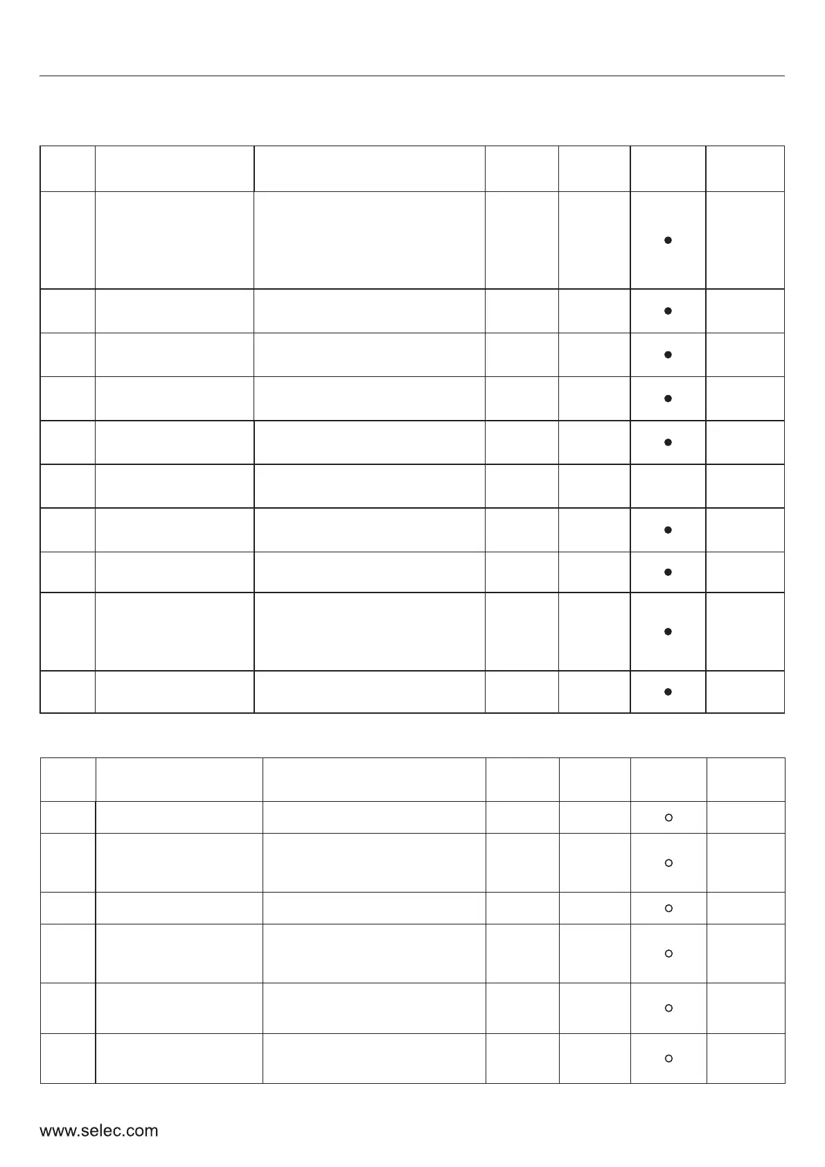
P4 – SCALAR CONTROL PARAMETERS
P4-00
V/f curve setting
0: General V/f
1: 1.5 Power V/f
2: 1.7 Power V/f
3: 2 Power V/f
4: Multipoint V/f
0
Yes
40400
P4-01
V/F Intermediate
Frequency 1 (F1)
0.0 Hz – F2 (P4-03)
1.0 Hz
Yes
40401
P4-02
V/F Intermediate
Voltage 1
0 – Rated Voltage (P3-01)
5 V Yes
40402
P4-03
V/F Intermediate
Frequency 2(F2)
F1 (P4-01) – F3 (P4-05)
5.0 Hz
Yes
40403
P4-04
V/F Intermediate
Voltage 2
0 – Rated Voltage (P3-01)
25 V
Yes
40404
P4-05
V/F Intermediate
Frequency 3(F3)
F2 (P4-03) – Rated
Frequency (P3-00)
25.0 Hz
Yes
●
40405
P4-06
V/F Intermediate
Voltage 3
0 – Rated Voltage (P3-01)
115 V
Yes
40406
P4-07
Torque boost
0-15.0 %
5.00 %
Yes
40407
Fun.
Code
Description Settings and Range
Default
Value
Basic
Setting
Modifi-
cation
M-bus
Address
P4-08
AVR Function
0: Disabled
1: Always Enable
2: Only Enable
during deceleration
0
Yes
40408
P4-09
Energy-efficient
running (EER)
0: Disable ; 1: Enable
0
Yes
40409
P5- INPUT FUNCTION PARAMETERS
P5-00
Lower Limit OF AI1
0.0 – 100.0 % 0.5 %
Yes
40500
P5-01
Corresponding
Setting of AI1
Lower Limit
0.0 – 100.0 % 0.0 %
Yes
40501
P5-02
Upper Limit OF AI1
AI1 Lower Limit – 100.0 % 100.0 %
Yes
40502
P5-03
Corresponding
Setting of AI1
Upper Limit
0.0 – 100.0 % 100.0 %
Yes
40503
P5-04
AI1 Input
Filtering Time
0.0 s- 10.0 s
0.1 s
Yes
40504
P5-05
AI1 Signal loss
threshold
0.0 to AI1 Lower Limit
0.5 %
Yes
40505
Fun.
Code
Description Settings and Range
Default
Value
Basic
Setting
Modifi-
cation
M-bus
Address

 Loading...