P6- Output Function Terminals
P6-00
0: Disable
1: Running
2: Direction
3: Fault Output
4: Pre-Alarm
5: Standby
6: Frequency arrived
7: Frequency detected
8: Upper Limit Frequency
9: Lower Limit Frequency
10: Setting Count Value
Received
11: Specified Count Value
Received
12: AI1 Signal Loss Threshold
reached
13: AI2 Signal Loss Threshold
Reached
Relay Output
Options
Default:
3
45
User Manual
0
Disable
The output terminal is not used for any task.
1
Running
The output terminal is used to denote that the drive is in
Running condition
2
Direction
The output terminal is used to denote the direction that the
drive is operating in. A HIGH signal would indicate REV
operation and a LOW signal would indicate FWD operation.
3
Fault Output
The output terminal is used to denote the presence of a
fault condition.
4
Pre-Alarm
The output terminal is used to indicate the presence of a
prealarm condition
5
Standby
The output terminal is used to denote that the drive is in
standby mode
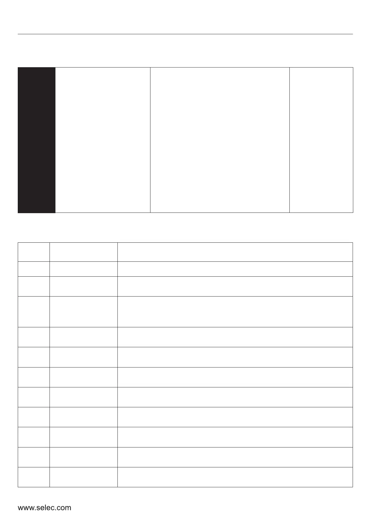
The above parameters set the function of the transistor and relay output terminals. These functions
are explained in the table below.
Set
Value
Function
Description
6
Frequency
Arrived
The output terminal is used to denote the FAR condition.
Refer parameter P12-14
7
Frequency
Detected
The output terminal is used to denote the FDT condition.
Refer parameters P12-12 and P12-13.
8
Upper Limit
Frequency
The output terminal denotes that the drive has attained the
upper limit of frequency (P0-09)
9
Lower Limit
Frequency
The output terminal denotes that the drive has attained the
lower limit of frequency (P0-10)
10
Setting Count
Value Reached
The output terminal denotes that the internal counter has
reached the setting count value (P12-15)

 Loading...