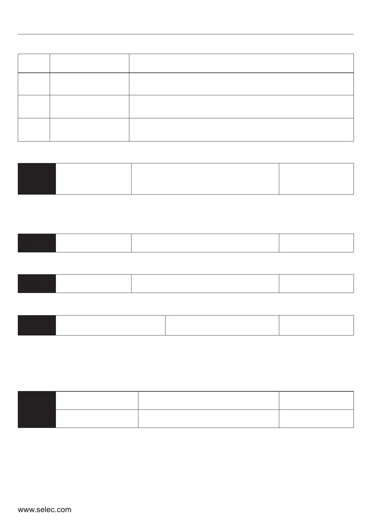
11
Specific Count
Value Reached
The output terminal denotes that the internal counter has
reached the specific count value (P12-16)
12
AI1 Signal Loss
Threshold Reached
Denotes that the input signal at AI1 has gone below the
user defined threshold value set in parameter P5-05
13
AI2 Signal Loss
Threshold Reached
Denotes that the input signal at AI2 has gone below the
user defined threshold value set in parameter P5-11
46
User Manual
Set
Value
Function
Description
P7 – PI Control Parameters
P7-00
PI reference
source
0: Keyboard 1: Analog channel AI1 Current
2: Analog channel AI2 Voltage
3: Analog channel AI2 Potentiometer
Default: 0
The PI Control parameters are used when PI control has been chosen as the frequency control
source in P0-01.
Choose the source which will provide the reference value for the PI control loop.
P7-01
PI set value
0.00 % to 100.00 % Default: 0.00 %
Choose the set value for the PI control loop. This setting is used when the value in P7-00 is 0.
P7-02
Feedback source
0: AI1 Current;
1: AI2 Voltage
Default: 0
Use this parameter to set the source of the feedback signal.
P7-03
PI output
characteristics options
0: Positive
1: Negative
Default: 0
Negative PI output characteristics: output frequency must be increased to make it balance when the
value of feedback signal is greater than PI set value, for example, PI control on unwinding tension.
Positive PI output characteristics: output frequency must be lowered to make it balance when the
value of feedback signal is greater than PI set value, for example, PI control on winding tension.
P7-04
Proportional gain
0.0 to 10.0
Default: 1.0
P7-05
Integral time
0.0 to 100.0 s
Default: 1.0 s