The signal applied to
either
the channel A
or
B vertical input
ma~:
be displayed independently.
Press
the
CHA.'\"
A
or
CHA.\' B
button
10
display either
tra~.
A signal
may
be connected to the
second channel
....
ithout affecting the displayed channel.
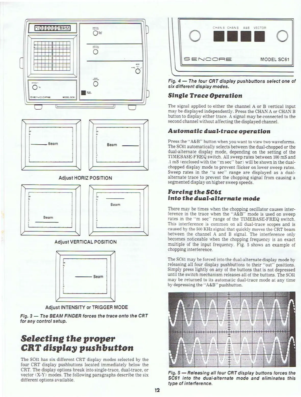
Fig. 4 -
The
four
CRT
display pushbuttons select one
of
six different display modes.
Slnllle
Trace
Operation
MODEL 5C61
o
••••
o
SEf'..JCQRE
I
":000000::""
I
-
0'"
,,,
I
'-'
-'-'
,
_.
,, ,
0
(
,
,
.. . .
-, .
, ,,
'0'
I.~:-
-J
-
0
.=
n
u
u
Automatic
dual·trace
operation
1--_
Be.m
8.,m
Adjust
HORIZ POSITION
Press
the" A&8" button
.....
hen you
.....
ant to vie
.....
t
.....
o
.....
a\·eforms.
TheSC6t automatically
selects between the dual-chopped
or
the
dual·alternate display mode. depending on the setting
of
the
TIMEBASE·FREQ s
....
itch.
All
s
.....
eep
rates
between
100
mS and
.1
mS (enclosed with the
"m
sec"
bar)
.....
ill be shown
in
the dual-
chopped display mode
to
prevent flicker
on
lo
.....
er
s
.....
eep rates.
S
.....
eep rates
in
the
"u
sec"
range
are
displayed as a dual-
alternate
trace
to pre\·ent the chopping signal from causing a
segmented display
on
highers
.....
eepspeeds.
Forclnll
the
SC6I
Into
the
dual-aJternate
mode
S
..
m
I ;
Adjust
VERTICAL POSITiON
---S
..
m
There ma)' be times hen the chopping oscillator causes inter-
ference in the
trace
hen the
"A&8"
mode
is
used
on
s eep
rates
in the
"m
sec'· range
of
the TJ:\IEBASE-FREQ s
itch.
This IOterference
is
common on all dual-Irace scopes and is
caused by the
500
KHz
signal that qUickly moves the CRT beam
bet
.....
een the channel
.-\
and 8 signal. The interference only
becomes
noticeable when the chopping frequenc)'
is
an exact
multiple of the input
frequency, Fig. 5 sho
.....
s
an
example
of
chopping interference.
The
SCSI
may be forced into the dual-alternate display mode by
releasing all four display pushbultons
to
their
"out"
positions.
Simply press lightly
on
any
of
the buttons that is not depressed
until thes
....
itch
mechanism releases all of the buttons. The
SC61
may
be returned to
its
automatic dual-trace mode
at
any time
b)·
depressing the ,.
A&8"
pushbutton.
Adjust
INTENSITY
or
TRIGGER MODE
Fig. 3 - The BEAM FINDER forces the trace
onto
the CRT
for any control
setup.
Selecting
the
proper
CRT
displa~
pushbutton
The
SC61
has six different CRT display modes selected by the
four CRT display pushbuttons located immediately below the
CRT. The display options break into single-trace. dual-teace.
or
"eclor
(X·'.t) modes. The follo\\ing
paragraphs
describe the six
different options 3\'ailable.
t
---t----r-
'::-.
-:FT
.-1
..
.,..?H-\
Fig. 5 - Releasing all four CRT display buttons forces the
SC61
into the dual-alternate mode and eliminates this
type
of
interlerence.
12