Range: 1second to 50 nanoseconds.
Set.ability:
=:20
nS
typical.
Peak-to-Peak Volts:
Function: Amplitude of intensified
area
measured.
Range
and
Specifications:
same
as
Peak·ta-Peak
\'olts above.
Sourcf:: Selected \l,;th channel A
or
B pushbutton.
Delta Time:
Function: Actual
time
of intensified
area
measured.
Accuracy:
Same
as
frequency
function abo\·e.
Accuracy
unaffected by settingof
horiwntal
or
"enical
controls.
Ranging: Microcomputer
automatically
places decimal
and
annunciator readingof mS
or
uS.
chance
of losing the intensified bar when the beginning and end
are
o\·erlapped.
It
also is helpful when you want to make a
measurement
before
and
after
a
certain
point
on
the waveform,
as
it is only necessary to
change
the position of one end of the
Delta
Bar
to
make
the two
measurements.
A given combination of settings of the
.4
BEGI~
and
.4
El\'D
controls resultsin the
bar
coveringapproximatelythe
same
per·
centage
of the CRT
screen
horizontally for any setting of the
TBLEBASE·FREQ sv.itch
or
the horizontal frequency vernier.
The beginning
and
ending positions
"ill,
therefore. need
to
be
readjusted
if
the sweep
rate
is
changed. However. the Delta
Bar
stays
in the
same
position on the
trace
when changing the
HORIZ
POSITION
control or activating the
lOX
expand function.
I/Deita
Time:
Function: Calculates equivalent frequency of Delta
Time
read-
ing.
Accuracy:
sameas
Delta Time.
Ranging: Microcomputer automatically places decimal and
annunciator readingof
Hz.
KHz.
or
MHz.
Digital Display:
Type:
Liquid cr)'stal v.ith high
temperature
fluid for fast
response
time
and high contrast.
~umberof
Digits: Six (resolution controlled by microcomputer).
Annunciators:
12
(controlled b)' microcomputer>.4.
A.
B. MHz.
KHz.
Hz,
uS.
mS.
VDC.
VPP.
AlB,
and
B/
A.
•
;_.:
•
.:lo
DELTAMEASU~EMEN'TS
...........
..
::...
.-
.....
."'"
.,...:.
0 0
.'.-
.=
•
•
wAVEfOIUl"'N"'~Tl[ll
'.".
---
The beginning and end of the Delta Bar
are
always timed iden·
tieaDy in
channel A and
B.
This allows the Delta
Bar
to
be
used
to
measure
the
time
delay between two signals,
or
to
mark
the
position of a
lransition in one channel
to
compare
the
time
relationshipof a transition in the second channel.
The amount of
intensit)· difference between the Delta
Bar
and
the background
is
a
fiXed
ratio. Use the I:'\'TE:\'SITY control to
adjust the
contrast
between the Delta
Bar
and
background
trace.
It
may
be desirable, for example, to
reduce
the setting of
the INTENSITY
control until the Delta
Bar
is the only
part
of
the
trace
shown. Increasing the setting of the
l:~'TENSITY
control slightly
causes
the non·intensified
areas
of the wave-
form to
also
show on the CRT
screen.
Setting
the
ll\'TE:\'SITY
control too high
may
resull in little
contrast
between the Delta
Bar
and background, leading
to
difficulty in seeing the begin·
ning and ending points.
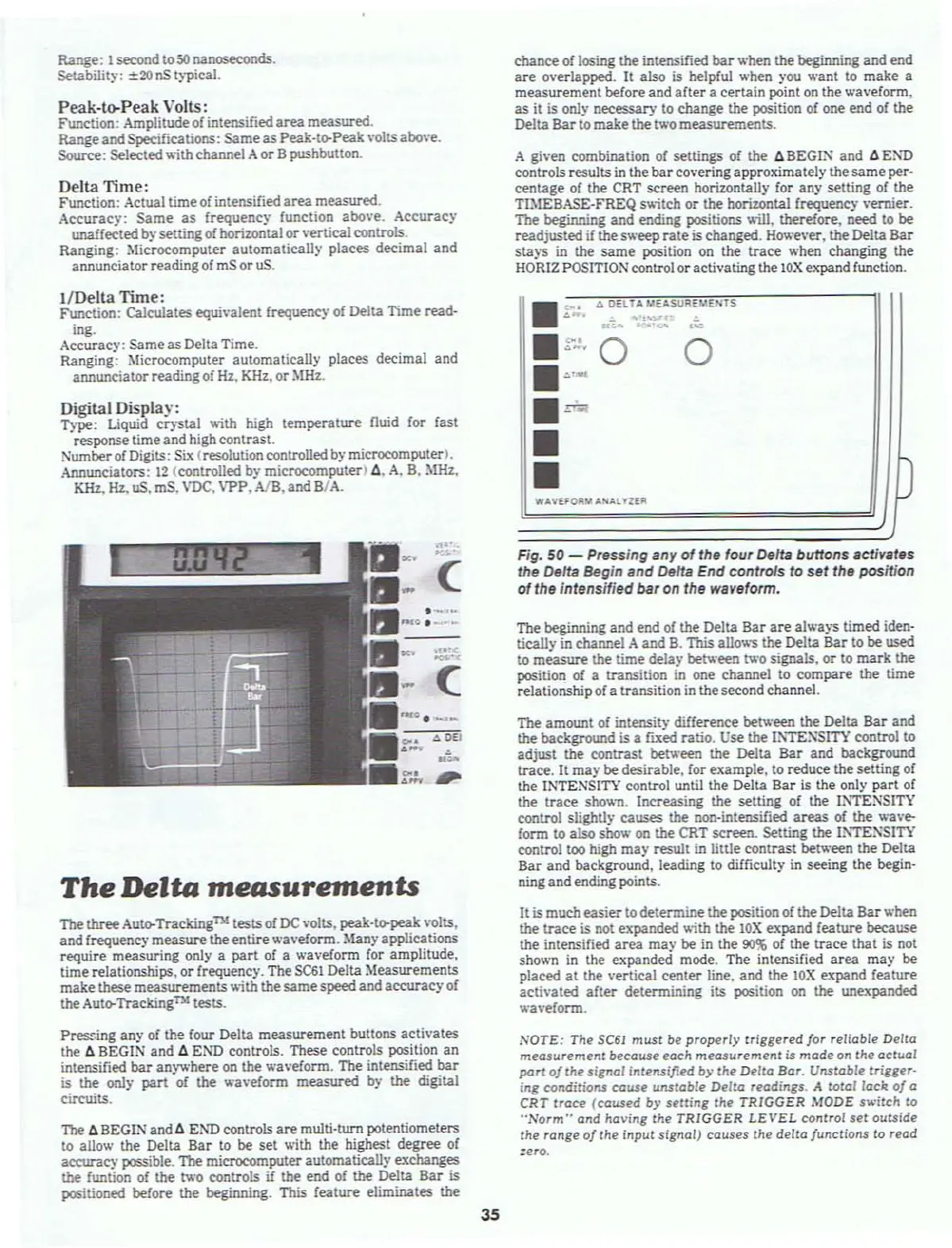
Fig.
50 - Pressing any
of
the four
DeHa
buttons activates
the
DeHa
Begin and Delta End controls to
set
the position
of
the Intensified bar on the waveform.
(
.:lo
DEI
-
~.
.-
II
·
....
~.'
.:
(
The
Delta
measurements
The
three
Auto-Tracking
nl
tests
of
DC
\'olts, peak·ta-peak
VOlts,
and frequency
measure
the
entire
wneform.
Manyapplications
require
measuring
only a
part
of a wa,'eform for amplitude.
time
relationships,
or
frequency. The
$C61
Delta Measurements
make
these
measurements
y,.ith
the
same
speed
and
accuracy
of
the
Auta-Tracking
lJr4
tests.
It is much
easier
to determine
the
position of the Delta
Bar
when
the
trace
is not expanded v.ith the
lOX
expand feature because
the
intensified
area
may
be
in the
90%
of the
trace
that
is not
shown in the expanded mode. The intensified
area
may
be
placed
at
the vertical
center
line. and the
lOX
expand feature
activated
afler
determining
its
position on the unexpanded
wa'·eform.
Pressing any of the four Delta
measurement
buttons
activates
the .4 BEGIN
and
.4
END controls. These controls position
an
intensified
bar
any
.....
here
on
the waveform. The intensified
bar
is
the only
part
of the waveform
measured
by the digital
circuits.
The
.4
BEGIN and.4 E!\'D ctlntrols
are
multi·turn potentiometers
to
allow the Delta
Bar
to be
set
y,.ith
the highest
degree
of
accurac" possible.
1be
microcomputer automatically exchanges
the
funtion of the
('A'O
controls if the end of the Delta
Bar
is
positioned before the beginning. This feature eliminates the
NOTE: The
SC61
must
be
properly
lrinered
lor
reliable
Delta
mecuurement
because each
measurement
is
made
on the
actual
part
o/the
signal
Interulfled
by
the
Delta
Bar. Unstable
trigger·
Ing
conditioru cause
unstable
Delta
r"adings. A total lack
0/
a
CRT
Irace
(caused
by
setting
the
TRIGGER
MODE switch to
"Norm"
and
ha
....
ing the
TRIGGER
LEVEL
control
set
outside
the range
0/
the input signal)
causes
the
delta/unctions
to
read
:ero.
35