2.
Adjust theTRIGGER LEVEL control fully clock'Aise.
NOTE:
The
CRT.houfd
be
blan.lt.
3,
Slov.-h·
adjust the TRIGGER LEVEL control in the coonter·
clock'Aise
direction until a
trace
just appears
on
theCRT
..
/l.'OTE:
After
the
proper
Irigger level
has
been
~tab'iJhed.
Ihe
TRIGGER
MODE
J\l.'ilch
ma),
be
returned
to
Ihe
"Aulo"
posi·
lion
wilhoul
affectin,
the
Irigger
poinl
on Ihe
.i,nal.
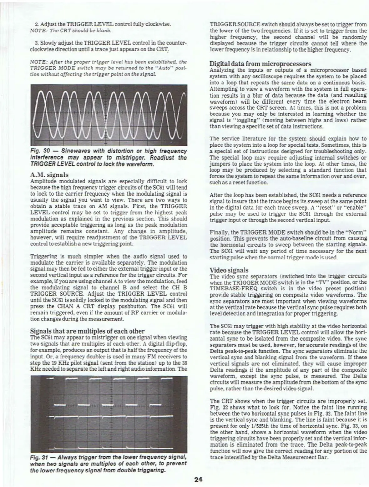
Fig,
30
- Sfnewaves
wHh
distortion
or
high frequency
interlerence
may
appear to mistrigger, Readjust the
TRIGGER
LEVEL
control to lock the waveform.
A.M.
signals
Amplitude modulated signals
are
especially difficult
to
lock
because the high frequency trigger circuits
of
the
SC61
\\ill tend
to
lock
to
the
carrier
frequency when the modulating signal
is
usually the signal you want to view. There
are
two ways to
obtain a stable trace
on
AM
signals, First. the TRIGGER
LEVEL
control may be set to trigger from the highest peak
modulation
as
explained
in
the previous section. This should
provide acceptable triggering as long
as
the peak modulation
amplitude
remains
constant. Any change in
amplitude,
tlfw'ever. will require readjuslment of the TRIGGER LEVEL
control to establisha new triggering point.
Triggering
is
much simpler when the audio signal
used
to
modulate
the
carrier
is available separatel)·.
The
modulation
signal
rna)' then be
fed
to either the external trigger input or the
second \'ertical input
as
a reference for the trigger circuits.
For
example,
if
you
are
using channel Ato view the modulation. feed
the modulating signal to channel B and select
the
CH
B
TRIGGER SOURCE, Adjust
the TRIGGER LEVEL control
until the
SC61
is
solidly locked to the modulating signal and then
press the
CHAN
A CRT display pushbutton. The
SC61
\\ill
remain triggered, even
if
the amount
of
RF
carrier
or modula·
tion changes during the measurement,
Signals
that
are
multiples of each other
The
SC61
may
appear
to mistrigger on one signal when vie'4ing
tv;o signals that
are
multiples
of
each other. A digital
ru~nop.
for example, produces
an
output that is half the frequency of the
input. Or, a frequency doubler is used
in
many
nt
recei\'ers to
step the
19
KHz pilot signal (sent from the station) up to the
38
KHz needed to separate the left and rightaudio infonnation. The
FIg,
31
- AhQlYs trigger from the lower frequency
sign,',
when
two
signals are multiples
of
each other,
to
prevent
the lower frequency signal from double triggering.
24
TRIGGER SOURCE s\\itchshould always beset to trigger from
the
lower
of
the two frequencies.
If
it is set to trigger from the
higher frequency. the second channel will be random!)'
displayed
because
the trigger circuits cannot tell where the
lower
frequency is
in
relationship to thehigher frequency.
Digital
data
[rom microprocessors
Analyzing the inputs or outputs of a microprocessor based
s)"'Stem
\\ith an)' oscilloscope requires the system to be placed
into a loop that repeats the
same
data
on
a continuous basis.
Attempting to view a waveform with the s)"stem in full opera-
tion
results
in
a blur
of
data
beeause the data (and resulting
waveform) will be different every time the electron beam
sweeps across the CRT screen.
At
times. this
is
not a problem
beeause )'ou
may
only be interested
in
learning whether the
signal
is
"toggling'" (moving between highs and lows) rather
than
vie\\inga specific set
of
data instructions.
The
service literature for the system should explain
how
to
place
the
s)"'Stem
into a loop for special tests, Sometimes. this is
a
s~al
set of instructions designed for troubleshooting only.
The
special loop rna)' require adjusting internal s\\itches or
jumpers to place the system into the loop. At other times, the
loop
may
be produced by selecting a standard function that
forees the system to repeat the
same
infonnation o\'er and o\'er.
such
as
a reset function.
After the loop
has been established. the
SC61
needs a reference
signal to insure
that the trace begins its sweep at the same point
in the digital
data
for
each trace sweep. A
"reset"
or henable"
pulse
may
be used to trigger the
SC61
through the external
trigger input or
through thesecondvertical input,
Finally. the TRIGGER
MODE
s\\itch sbould be in the
"Nonn"
position. This pre\'ents the auto-baseline circuit from causing
the horizontal circuits to sweep between the starting signals.
The
SC61
will wait any period of time necessary for the next
starting
pulsewhen the nonnal trigger mode
is
used,
Video signals
The video sync separators (s\\itehed into the trigger circuits
when
theTRIGGER
~toDE
S\\iteh is in the "TV" position, or the
TlMEBASE-FREQ s\\itch is
in
the video preset position)
pro\ide
stable triggering on composite
\ideo
wavefonns. The
sync separators
are
most important when viewing waveforms
at the vertical
rate
beeause the vertical sync pulse requires both
level detection and
integration for proper triggering.
1be
SC61
may
trigger \\ith high stability at the video horizontal
rate
because
the TRIGGER LEVEL control will allow the hori-
zontal
sync to be isolated from the composite video. The sync
separators must be used, however. for accurate readings
of
the
Della
peak-to-puk function. The sync separators eliminate the
vertical sync and blanking signal from the waveIonn.
If
these
vertical signals
are
not eliminated. they \\ill
cause
improper
Delta readings
if
the amplitude of any part
of
the composite
wavefonn, except
the sync pulse.
is
measured. The Delta
circuits
\loill
measure the amplitude from the bottom of the sync
pulse. rather than thedesired video signaL
The CRT shows when the trigger
circuits
are
improperly set,
Fig.
32
shows what to look for. Notice the faint line running
between
lhe two horizontal sync pulses in Fig.
32.
The faint line
is
the vertical sync and blanking. The line is faint because it
is
present for only 1/525th the time of horizontal sync. Fig.
33.
on
the other hand. shows a horizontal
wavefonn when the video
triggering circuits have
been properlyset and the vertical infor·
mation is eliminated from the
trace. The Delta peak·tl>'peak
function \\ill
now
give the correct reading for any portion of the
trace
intensified by the Delta
~teasurement
Bar.