6.
Divide the actual frequency step (step
5)
by
the equivalent
frequency
(step~)
and multiply the results times360·.
To
measure the ratioof two frequencies:
1.
Apply
the signals to the channel A and Binputs.
PhaseShirt =
FREQ
l/LLTIME
x360'
NOTE: Both channels
must
havi" sufficient amplilude
to
operate
the FREQfunctions. See page33for details.
2.
Press the
"AlB
or
B/A"
button.
NOTE:
If
thi"
channel B signal
is
leading the channel A signal
phose (the results
are
greater
than
js{}O),
you
may
calculate the
leading
phase
by
subtracting
IS{}
from
the
above calculations,
or
use thefol/owing procedure.
To
calculateleading phase:
I. Press the
1/
6 TIME button.
2.
Observe the lap waveform as
you
adjust the 6 BEGIN
control until the beginning
of
the Delta Measurement Bar
is
at
the very topof thesignal.
3.
Adjust the .6END control until the end
of
the Delta Measure-
ment Bar
is
at
the very top
of
the first cycle
of
the bottom wave-
form to the left of the beginning point.
4.
Read the equivalent frequency from the digital display.
5.
Press
the FREQ button for either channel A or B (the
frequency will be the
same
for both channels).
6.
Divide the actual frequency (step
5)
by
the eqUivalent
frequency (step
4)
and multiply the results times360·.
FrfUluenc~
ratio
tests
The
SC61
automatically calculates the ratio
of
the rrequencies
applied
to
channel A and B
by
pressing the ';A/B or B/A"
button. The ratio test is used to confirm that a fixed or program-
mable digital divider
is
dividing the input signal properly, or
that a frequency multiplierstage
is
multiplying correctly.
The microcomputer
not
only calculates the ratio, it also indicates
whether the frequency in channel A or B is larger, If, for
example, the channel A signal is higher
in
frequency than
channel
B,
the display annunciator
.....
ill
show
"AlB".
If,
on
the
other hand, the channel B signal has a higher frequency, the
annunciator will show
"B/
A". The ratios will always
be
shown
as
a number 1to
999,999.
•
•
0
•
•
0
•
~
•
••
•
..
V"AVEFORM
ANALYZER
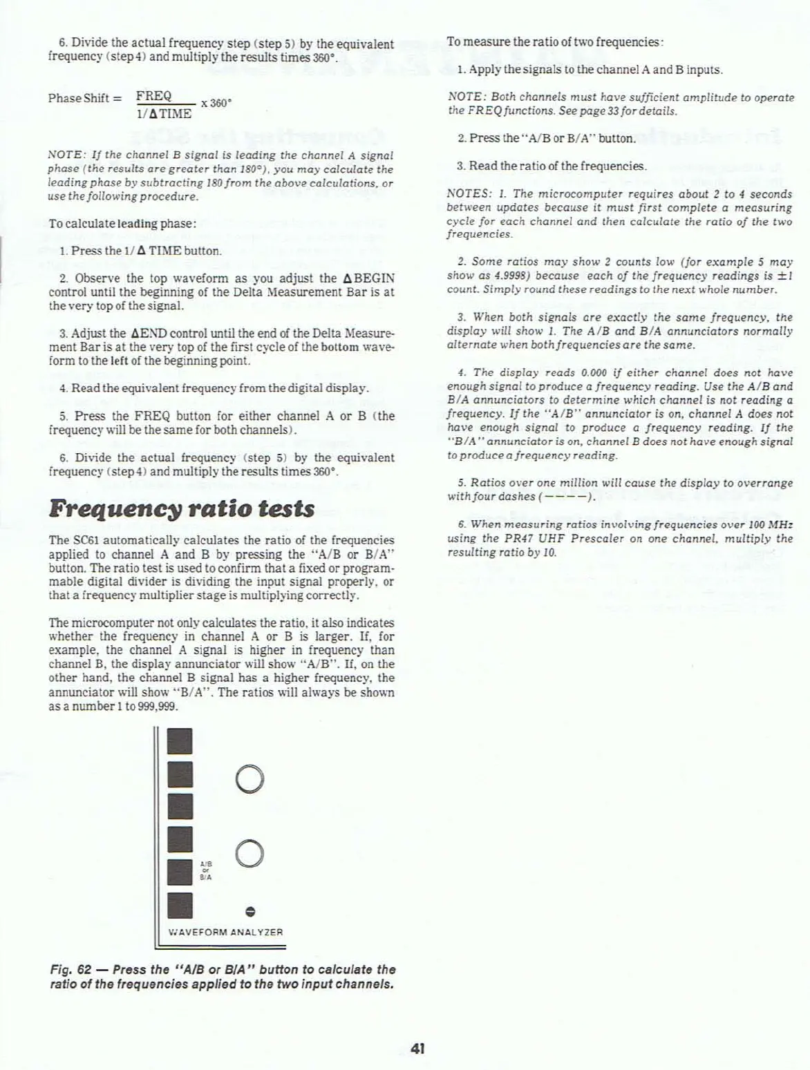
Fig, 62 - Press the "AJB or
BlA"
button to calculate the
ratio of the frequencies applied to the two
input
channels.
41
3.
Read the ratio
of
the frequencies.
NOTES:
I.
The
microcomputer
requires
about
2 to
of
seconds
between updates because
it
must
first complete a measuring
cycle for each channel and Ihen calculate the ratio
of
the
two
frequencies.
2.
Some ratios
may
show 2
counts
low (for
example
5
may
show as 4.9998) because each
of
the frequency readings
is
±l
count. Simpiy round these readings to the
next
whole
number.
3.
When both signals
are
exaclly
the
some
frequency,
the
display will show
l.
The
AlB
and BIA annunciators normally
alternate
when both frequencies
are
the same.
4.
The display reads 0.000
if
either channel does not have
enough signal to produce a frequency reading. Use the
AlB
and
BIA annunciators
to
determine
which channel is not reading a
frequency.
Ij
the
"AIB"
annunciator is on, channel A does not
have enough
signal
to produce a frequency reading.
If
the
"BIA
,. annunciator is on, channel B does not have enough signal
toproduceafrequency
reading.
5.
Ratios
over one million will couse the
dispiay
to
overrange
with
four dashes
(----).
6.
When measuring ratios involving frequencies over 100 MHz
using the PR47 UHF Prescaler on
one
channel,
multiply
the
resulting
ratio by
10.