The optional TP212
Transient
Protector
Probe
a1lo~-s
\'oltage
measurements
to
10
KV
~ith
1%
accuracy.
The TP212
dhides
the
input signal by
10.
requiring the
decimal
place of
the
displayed \'alue to be moved one place to
the
right for
the
actual
circuit voltage.
For
example. a reading of
395
volts represents a
circuit \'oltage of
3950
volts.
Theoptional
HP200
High Voltage
Probe
allo
....
-s
voltage
measure-
ment to
50
KV with
2q;
accuracy,
The
HP200
divides
the
input
signal
by
100.
requiring
the
decimal place of the displayed
value
to be mO\'ed t
.....
o places to
the
right for
the
actual
circuit
\·oltage.
For
example. a reading of 395 volts
represents
a circuit \'oltage
of39.5OO\'0Its,
NOTE:
The
high
\lo/tage probes increase
the
input
impedance
by
0
faclor
of
10
or
100.
allowin,
measurements
in high
impedance
circuits with minimum
DC
loading.
The
TPZ12
results
in
a 150
megohm
input impedance,
or
Ihe HP200
results
in a JSoo megohm (1,5 gigohm) input impedance.
r-----WARNING
-------,
Do
not
attempt
to
perlonn
any
high \'Oltage testing
until you have
completely read
and
understood
the
following warnings
and
instructions!
1.
'ever
attempt
to
measure
more
than
2000 \'olts
without
the
use
of
a high voltage
probe.
To
do
SO
may
damage
the
SC61.
the
equipmenl
under
test, and/or
cause a
severe shock hazard to
the
operator.
2.
If
the
common
lead
should
become
detached
during a high \'oltage
measurement,
immediatel)
remove
power
to
the
circuit
under
test.
Do
not
touch
the
lead,
the
SC61.
or
the
high voltage
probe
until
the
power has
been
removed as there
is
a possibility
of
a
severe shock hazard.
Be
sure
the
SC61
functions
properly before continuing to
use
it
after
power
to
the
circuit has
been
remO'-ed.
Damage
to
the
SC61
because
of
a
detached
ground
lead
is
not
CO\'ef"ed
by
any
warranty.
3.
If
the
SC61
probe
should
become
detached
from
the
hi$h \'oltage
probe
during
a
measurement,
imme(halely remove
the
power
to
the
drcuit
under
test. Do not touch
the
high voltage
probe
until the
power has
been
removed
and
the
high voltage
is
dis,
charged as
there
is
the
possibility
of
a seo.ere shock
hazard.
4.
If
the
high \'oltage
probe
must
be
held during a
measurement,
do
so
\\ith
extr~e
caution.
Be
sure
the
connection
to
the
probe
and
the
ground lead are
firmly
anached.
Hold
the
probe
behind
the
molded
safely rings
to
prevent
the
possibility
of
contacting the
high voltage test point
or
to
prevent arcing across the
probe
to your body.
5. Remove
the
po
.....
er
to
the
circuit
under
test
before making connection
to
the
test point
or
before
disconnecting
the
high \'Oltage
probe
from
the
circuit.
To
measure
over
2000
volts DC:
1.
Remo\'e po
.....
er
from
the
equipment
in
\o\'hich
the high
\'oltage is to
be
measured.
2.
Connect
the
39G157
probe
to
either
of
the
DCV
lX
jacks.
Be
sun~
Iheconnectoris firml)'
sealed.
3.
Slide
the
tip of
the
39G
157
into the opening
at
the
rear
of
the
32
high voltage probe, Be
sure
tbe
tip is
nrml~'
seated
in the con·
nectar
inside
the
probe in such a wa)' Ihat it cannot become
delached during
the
measu~ment.
4. Secure!)'
altach
the
black ground lead supplied with
the
SC61
to
the
common
point of
the
circuit to
be
tested. Be
sure
Ihis
lead
cannot become del3ched during
the
high voltage measure-
ment. Connecl
the
other end
to
the
GROUr-.'D
jack
on the
SC61.
,\'OTE: The common point must be
referenced
to
earlh
ground.
TheSC61
chassis
musl not
be
floared abo,"e
earlh
ground
during
a
measurement. Use
an
isolation IraTlSformer on Ihe circuit
being lested
if
necessary
10
isofate Ihe common
point
from
earth
ground.
5, Connect
the
high voltage probe
to
the
lest
point to
be
measured
In
such a
wa)'lhallhe
probe does not h3\'e to be held
during Ihe
measurement.
If
it must be held. do
so
with
extreme
caution
(see
warning
_-I
at
lefO.
6.
Press the
"DC\-'
DIGITAL
READOlJ'T pushbutton for
the
SC61
channel used.
7.
Apply
power
to
~
equipment
under
test.
8.
Multiply the
reading
on
the
digital display by
10
when using
the
TP212
or
by
100
when
using
the
HP2OO.
9. Remo'"e
pcnr.·er
to
the
equipmenl
under
test before discon-
DeUiDg the
high
\'oItage probe.
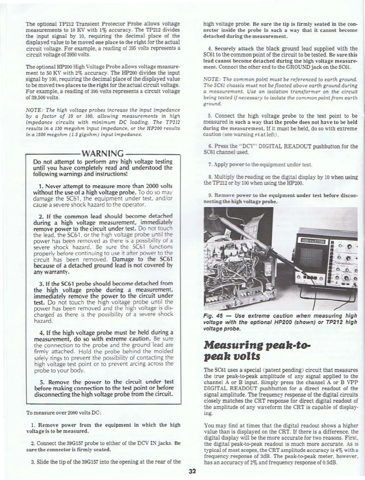
Fig. 45 -
Use
extreme caution when measuring
hif1h
voltage with the optiona' HP200 (shown)
or
TP212 high
voltage probe.
Measuring
pfUJk.to-
pfUJkvolts
The SQiI uses a special
(patent
pending) circuit that
measures
the
true
peak-ta-peak
amplitude
of
any
signal applied to the
channel
A
or
B input. Simply
press
the
chaM~1
A
or
B VPP
DIGITAL READOl.iT pushbutton for a
direct
readout
of the
signal
amplitude. The frequency response of the digital circuits
closely
matches
the
CRT response for
direct
digital readout of
the
amplitude
of any wa\'eform
the
CRT
is
capable
of display-
ing.
You
may
find
at
times that the digital readout shows a higher
\'alue
than
is displayed on
the
CRT.
If
there
is a difference.
the
digital display will be
the
more
accurate
for two reasons.
First.
the
digital peak-la-peak
readout
is much
mor~
aceurate.
As
is
typical of mostscopes.
the
CRT
amplitude
accuracy
is
-1%
\lith
a
frequency
response
of 3dB. The peak-ta-peak
meter.
howe\'er.
has
an
accuracy
of~
and
frequency response of
O_SdB.