Indirect
eonneetlolU
with
the
PL:Z07
The
39(;183 probes provide
1(1'1.
capacitive loading and high
\'oltage protection adequate for most measurements. The
measuring capabilities of the
SC61
may
be
extended even
further
by
using inducth'e pickup of signals v.;th the
PU07
RF
Pickup
Loop.
Peak-t~peak
readings made
\lith
the
PL207
are
relative.
You
can
confirm a signal is present,
its
W3\'eshapeand
frequenc)'
as
.....
ell
as
.....
hether
the
amplitude is increasing
or
decreasrng. .
The
DC
or capacitive loading of any oscilloscope probe
may
affect
some
high impedance/high frequency circuits, such
as
oscillators. Simply connec! the
PL207
in place
of
the
390183
probe and position the loop close to a coil or capacitor
in
the
circuit
Mo\'e the loop
near
the component until a
clear
wave-
form
appears
on the CRT.
II
may
be necessary
to
change
the
loop orientation for best results.
The
PU07
may
also be
used
to
sample
signals in circuits
\loith
operatingpotentials above
2000
volts. Use
extreme
caution
.....
hen
working around
high voltage circuits to
pre"ent
a shock
hazard
or
direct
contact
between the PL20i
and
a high voltage point,
Hold
the PL207
se"eral
inches from
the
signal's
source. The
PI..207
acts
like
an
antenna to pick up the signal
and
supply it to
the
SC61
input.
"="<
~
"'1:::::S:::::==:::;;~~::=J
It:i-'~
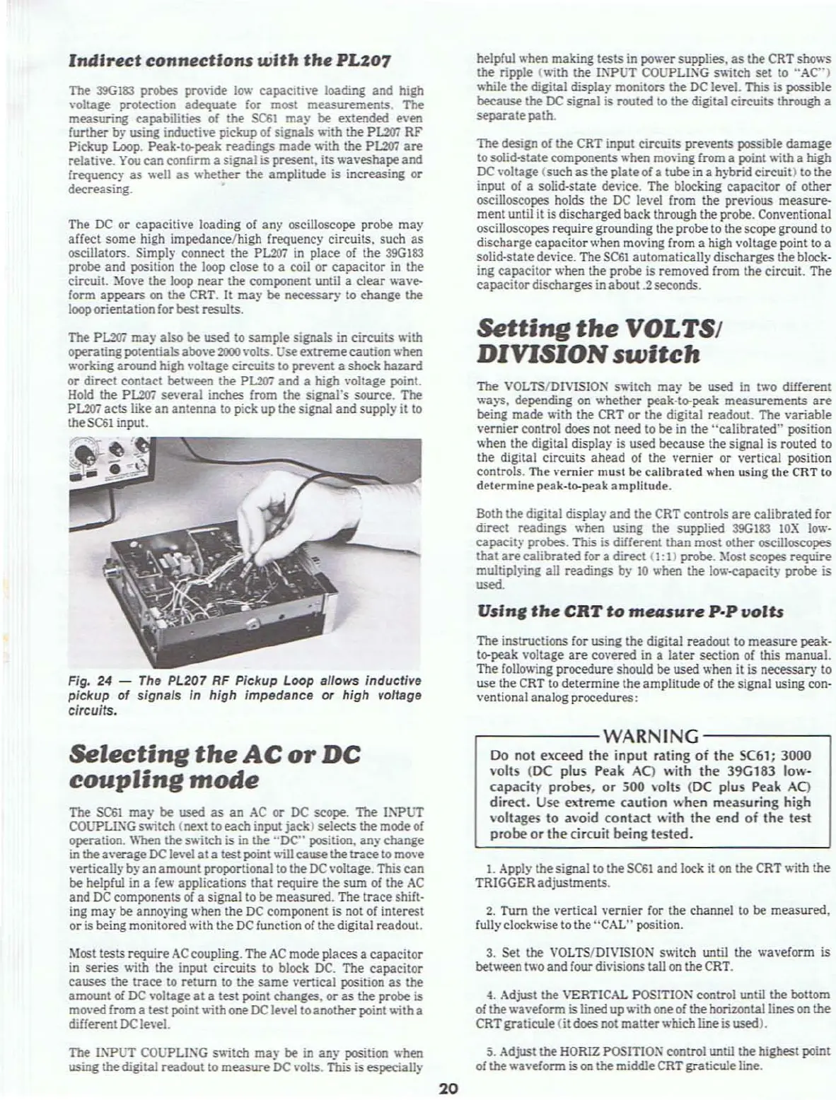
Fig, 24 -
The
PL207
RF
Pickup Loop allows inductive
pickup
of
signals in high impedance or high voltage
circuits.
Selecting
the
AC
or
DC
coupling
mode
The
SC61
may
be
used
as
an
AC
or
DC
scope. The
11\'PUT
COUPLLl'oiG
s>Aitch
(next to
each
input
jack)
selects the mode of
operation.
When the s
....
itch
is
in
the
"DC"
position,
any
change
in
the
a"erage
DC
le
...
el
at
a test point
"ill
cause
the
trace
to mO"e
"ertically
by
an
amount proportional to the
DC
,·oltage. This
can
be
helpful in a few applications
that
require
the
sum
of the
AC
and
DC
components of a signal to
be
measured. The
trace
shiH·
ing
may
be
annoying when the
DC
component is not of interest
or
is being monitored with the
DC
function of the digital readout.
Most tests
require
AC
coupling. The
AC
mode places a
capacitor
in
series
"ith
the input circuits to block DC. The
capacitor
causes
the
trace
to
return
to the
same
vertical position
as
the
amount of
DC
,'oltage
at
a test point changes.
or
as
the probe is
mo
...
ed
from a test point
....
ith
one
DC
le
...
el to
another
point
....
ith
a
different
DC le"eJ.
The
P.\"PUT
COUPLlXG switch ma}'
be
in
any
position
.....
hen
using the digital readout to
measure
DC
...
olts. This is especially
20
helpful when making
tests
in pov,'er supplies,
as
the CRT sho
.....
s
the ripple
("ith
the
I~"PUT
COUPLlXG
s>Aitch
set
to
"AC")
.....
hile the digital display monitors the DC le
...
eL
This is possible
because
the DC signal is routed to the digital circuits through a
separate
path.
The design of the CRT input circuits prevents possible
damage
to solid-statecomponents when moving from a point
"ith
a
high
DC
voltage (such
as
the
plate
ofa tube in a hybrid circuit) to the
input of a solid·state
device. The blocking
capacitor
of
other
oscilloscopes holds the
DC
le
...
el from the pre,oious measure-
ment until it is discharged back through the probe. Conventional
oscilloscopes requiregrounding the probe to the scopeground to
discharge
capacitor
when mo"ing from a high "oltage point to a
solid·state device. The
SC61
automatically discharges the block·
ing
capacitor
when the probe is removed from the circuit.
The
capacitor
discharges in about
.2
seconds.
Setting
the
VOLTSt
DIVISION
switch
The
VOL
TS/DIVlSIO:-J s
....
itch
ma~'
be
used
in t
.....
o different
.....
ays. depending
on
.....
hether
peak·ta-peak
measurements
are
being
made
....
ith
the CRT
or
the digital readout. The variable
vernier
control does not need to
be
in the
"calibrated"
position
when the digital display is used because the signal is routed to
the digital circuits
ahead
of the
vernier
or vertical position
controls.
The
vernier
must be
calibrated
.....
hen using the CRT to
determine
peak·to-peak amplitude.
Both the digital display
and
the CRT controls
are
calibrated
for
direct readings
.....
hen using
the
supplied 39G183
lOX
low·
capacity
probes. This is different than most
other
oscilloscopes
that
are
calibrated
for a direct
(I:
1) probe. Most scopes
require
multiphing
all readings by
10
.....
hen the lo"
..
-eapacity probe is
"""'-
Vsln,
the
CRT
to
mellSure
p.p
&lolts
The instructions for using the digital readout to
measure
peak.
to-peak voltage
are
covered in a
later
section or this manual.
The following procedure should be used
when it is necessary to
use the CRT
to
determine the amplitude or the signal using con·
ventional analog procedures:
r----WARNING
-------,
Do
not
exceed
the
input
rating
of
the
SC61;
3000
volls
(DC
plus
Peak
Aq
with
the
39G183
low-
capacity
probes.
or
.500
"olts
(DC
plus
Peak
AQ
direct.
Use
extreme
caution
when
measuring
high
"ollages
to
a\'oid
contact
with
the
end
of
the
test
probe
or
the
circuit
being
tested.
1.
Apply the signal
to
the
SC61
and
lock it
on
the CRT
.....
ith
the
TRIGGERadjustments.
2.
Tum the vertical
vernier
for the channel
to
be
measured,
fully
clockwise to the "CAL" position.
3. Set the VOLTS/DIVISION s
.....
itch until the
.....
aveform is
bet
.....
een t
.....
o and four divisionstall on theCRT.
4. Adjust
the
VERTICAL POSITION control until the bottom
or the wa"eform is lined up
.....
ith
one of the horizontal lines on the
CRT
graticu1e (it does not
matter
whichline is used).
5.
Adjust the HORIZ POSITIO:\ control until the highest point
of the
.....
aveform is
on
the middle CRT graticuleline.