6.
Count the
number
of divisions occupied by the waveform.
Remember
that each minor
mark
on the graticule
represents.2
major
divisions.
i.
Multiply the total
number
of
major
divisions and
parts
of a
division by the setting of the VOLTS/DIVISION switch to
determine the
total peak-to-peak amplitude of the signal.
Remember
that
it is not necessary to move the decimal
if
the
supplied
lOX
low-eapacit)· probes
are
used.
If
the DP226 Direct
Probe
is used, divide the resulting number by ten (move the
decimal one placeto theleft).
Using
the
CRT
to
meASure
DC
levels
The digital readout should
always
be used to
determine
the
a\'erage
DC
level
at
any
test point. The digital section of the
SC6l provides results
that
are
approximately
60
times more
accurate
than using the CRT display. The digital
DCV
circuits
automatically determine
the
average
level of the
AC
com-
ponent of a signal
and
add this level to the
DC
bias. These
readings
agree
....
ith
the
DC
voltagesshown on schematics.
There
are
times when you need to know the DC level of a portion
of a waveform, such
as
the
"on"
or
"off"
level of a digital signal.
These
measurements
are
sometimes called the "absolute value"
or the hOC plus
Peak
AC" value of the signal. These measure-
ments
must
be
made
with the CRT because the digital test
sho
....
-s
the
average
DC
level.
The following
procedure should
be
used to determine the
absolute valueof
any
part
of a waveform:
r-----WARNING------,
Do
not
exceed
the
input
rating
of
the
SC61; 3000
volts
(DC
plus
Peak
Aq
with
the
39G183
low-
capacity
probes,
or
500
volts
(DC
plus
Peak
Aq
direct.
Observe
extreme
caution
when
measuring
high
voltages
to
avoid
contact
with
the
end
of
the
test
probe
or
the
circuit
being
tested.
1. Apply the signal to the
SC61
and
lock it
on
the CRT with the
TRIGGER adjustments.
2.
Turn
the vertical
vernier
for the channel )'ou wish
to
measure, fully clockwiseto the "CAL" position.
3.
Set the VOLTS/DIVISION switch to a
marked
position
that
is between one-half
to
one-eighth the expected
DC
level.
If,
for
example, the
expected voltage is
10
volts, the switch should be
set
to the
';2"
or
"S"
position.
4.
Set the I!\'PUT COliPLING switch to the
"ground"
position
to
establish a zero reference point. (NOTE:
The
TRIGGER
MODE
switch
must
be in
the
"Auto"
position
in
order
to
produce
Q trace
with
no
input
signal.)
5.
Adjust the position of the
trace
(with the input grounded)
using the VERTICAL POSITION
conlrol until it is on
any
of the
CRT graticule lines. This is
your
zero
reference
line.
6.
Move the INPUT COUPLfNG switch
to
the
"DC"
position.
i.
Decide what
part
of the waveform should be
measured
(the
TRIGGER
adjustments
and TIMEBASE-FREQ switch
may
need to
be
adjusted to show the necessary detail) and use the
HORIZ POSITION control
to
place that
part
of the waveform on
the
center
CRT line.
Do
not
mO\'e
the VERTICAL POSITIOX
control.
as
this will change )'ourzero
rderence.
21
8.
Count the number of divisions from the zero reference line
(step
5)
to the point you want to
measure
on
the waveform.
Remember
that
each
minor
mark
on the graticule
represents.2
major
divisions.
9.
Multiply the total
number
of
major
divisions
and
parts
of a
division by the setting of the VOLTS/DIVISION switch to deter-
mine the absolute value.
Remember
that it is not necessary to
move the decimal if the supplied
lOX
low-capacity probes
are
used.
If
the DP226 Direct Probe is used, divide the resulting
number by ten (move thedecimalone place to the left).
Tips on measuring
DC
volts
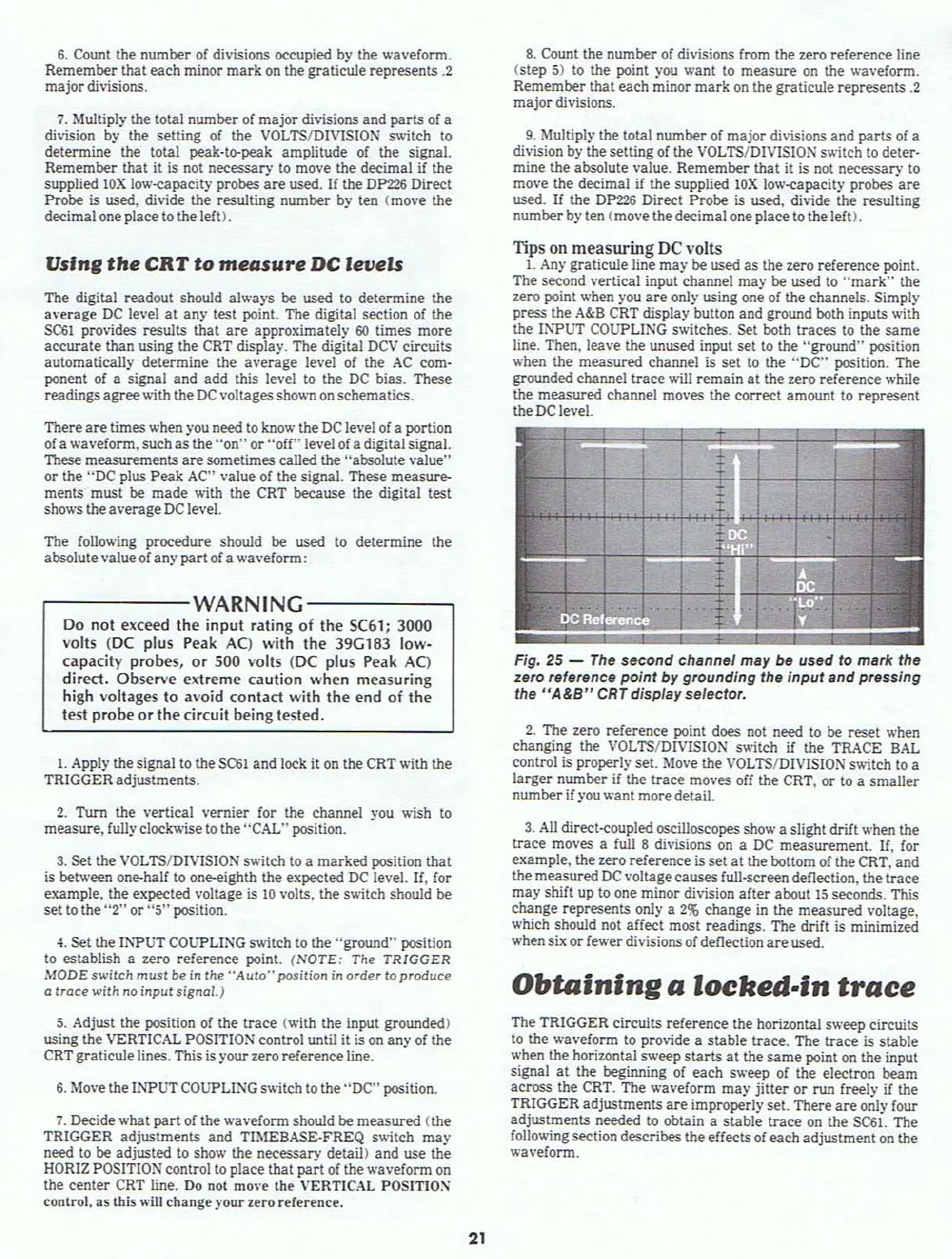
1. Any graticule line
may
be used
as
the zero reference point.
The second vertical input channel
may
be used to
"mark"
the
zero point when you
are
only using one of the channels. Simply
press the
A&B CRT display button and ground both inputs with
the Il'WUT COUPLING switches. Set both
traces
to
the
same
line. Then, leave the unused input
set
to
the "ground" position
when the
measured
channel is
set
to
the
"DC"
position. The
grounded channel
trace
will
remain
at
the zero reference while
the
measured
channel moves the correct amount to
represent
the DC level.
Fig,
25
-
The
second channel may
be
used to mark the
zero reference
point
by grounding the
input
and pressing
the
"A&B"
CRT
dispfay seiector,
2.
The zero reference point does not need to be
reset
when
changing the VOLTS/DIVISION s
....
itch
if
the TRo\CE SAL
control is properly set. Move the VOLTS/DIVISION switch to a
larger
number if the
trace
moves off the CRT.
or
to a
smaller
number if you
.....
ant
moredetail.
3.
All
direct-coupled oscilloscopes show a slight drift when the
lrace
moves a full 8 divisions
on
a DC measurement.
If,
for
example,
the zero reference is
set
at
the bottom of the CRT, and
the
measured
DC
voltagecauses full-screen deflection, the
lrace
may
shift up
to
one minor division
afler
about
15
seconds. This
change represents only a
2%
change
in the
measured
voltage,
.....hich
should not affect most readings. The drift is minimized
when six
or
fewer divisions of deflection
are
used.
Obtaining
a
locked-in
trace
The TRIGGER circuits
reference
the horizontal s
.....
eep circuits
to the waveform to
pro\'ide a
stable
lrace.
The
trace
is
stable
when the horizontal sweep
starts
at
the
same
point
on
the input
signal
at
the beginning of
each
sweep of the electron beam
across the CRT. The waveform
may
jitter
or
run freely if the
TRIGGER
adjustments
are
improperly set. There
are
only four
adjustments
needed
to
obtain a
stable
trace
on the SC6l. The
following section describes
theeffectsof
each
adjustment
on
the
waveform.