Check the probes' compensation
by
connecting them to the
PROBE
CO:\IP
jack
on
the front panel. The resulting
CRT
display
should have a flat top and bottom
....
ilh
square corners. The capa-
citor should be adjusted
if
there
is
any overshootor rounding.
NOTE:
The
probe
compsignal
ha§square
edges.
but
may
nol
be
an
exaclly
symmelrical
square
wove.
The
dUfy
cycle.
exocl
frequency
or
amplitude
is not
important
in
its
application
of
lesting
probe
compensalio!'.
To
compensatethe probes:
using a direct probe. These disadvantages
are
related
to
all
direct probes,
not
only the
DP226.
First, the direct probe does not isolate the capacity of the input
circuits and the probe cable from the circuit. This added capa·
citance may cause some circuits to change operating points.
Second. the
DC
input impedance of the measuring system
is
reduced from
10
megohms to I megohm, which may load some
high impedance
DC
circuits. Third, the frequency response
is
limited to
15
MHz.
This third point rna)' require a bit more
explanation.
Connecting
to
a
generator
output
The direct probe, therefore. is useful
in
applications requiring
added sensitivity on signals below
15
MHz.
It
should not,
however. be used
for
most measurements.
Finally. remember that the
SC61
CRT
and digital display
are
both calibrated for a
lOX
low-<:apacity probe. The readings must
be divided b)'
10
when
used
.....
ith a direct probe.
It
would seem that a direct probe would be
no
more than a piece
of coaxial cable
....
ith
a connector
on
one end and a probe tip
on
the other end. This,
ho
.....
ever. does not
.....
ork
well
because the one
megohm impedance
of
the
SC61
input does
not
terminate the
characteristic impedance of the cable, resulting
in
standing
waves
on
signals with fast risetimes. Thestanding waves add
to
the measured signal, causing ringing and other waveform
distortion. High quality direct probes, such
as
the
DP226,
use a
special resistance wire (with several ohms per
foot
of
DC
resistance)
as
the center conductor of the coaxial cable. The
resistance damps the standing waves to eliminate the ringing.
The resistance,
ho
.....
ever, also reduces the usable frequency
response because the resistance
of
the wire
is
in
series with the
input capacitance
of
the scope.
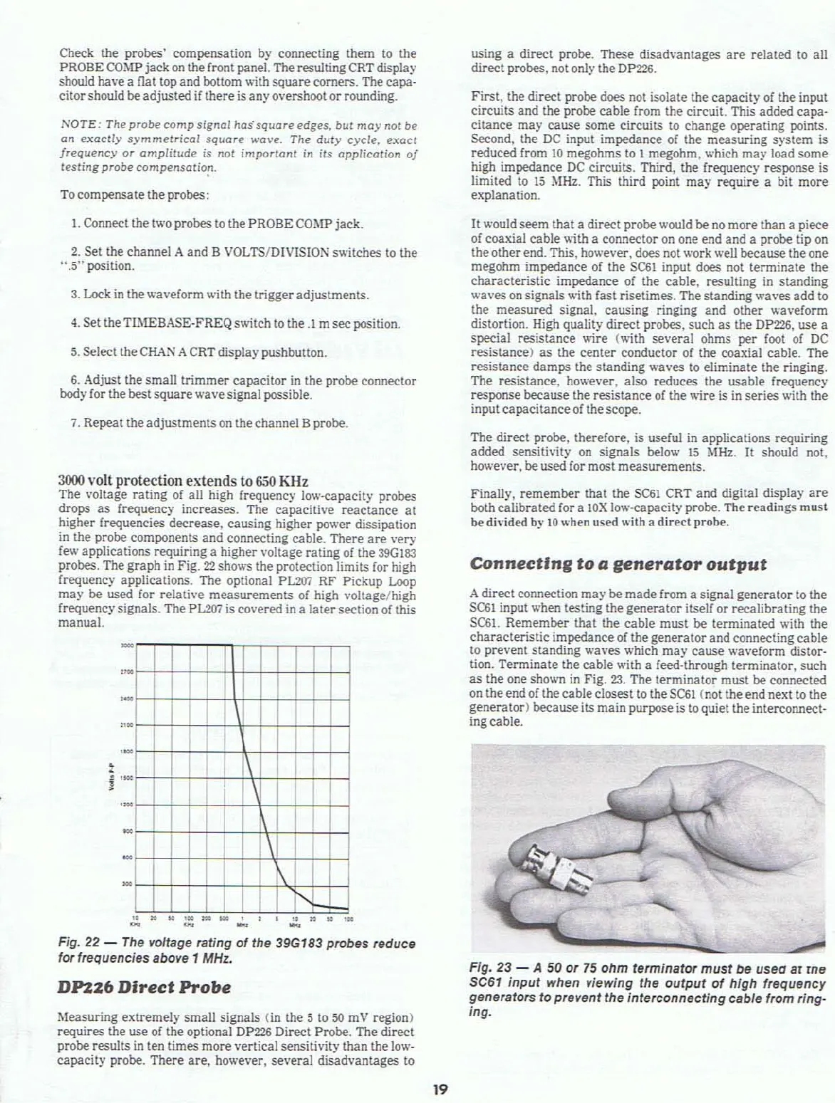
Adirect connection may be made from a signal generator
to
the
SC61
input
.....
hen testing the generator itself or recalibrating the
SC61.
Remember that the cable must be terminated with the
characteristic impedanceof the generator and connecting cable
to
prevent standing waves which may cause waveform distor-
tion. Terminate the cable with a feed-through terminator. such
as
the one shown
in
Fig.
23.
The terminator must be connected
on
the end
of
the cable closest to the
SC61
(not the end next to the
generator) becauseits main purpose is
to
quiet theinterconnect-
ingcable.
Fig.
23
- A 50 or
75
ohm terminator
must
be usea ar rne
SC61 input when viewing the
output
of
high frequency
generators
to prevent the interconnecting cable from ring-
Ing.
I
I
I I
•
I I I I
I
I
I I I
1\
I I I
I I
I I
I
I I I
I I
I I
I I
1\
I
I
I I I I
1'1
I
••
......
,
.....
_,
.. "
....
,
..
"'" "'"
- -
"
•
1.
Connect the
two
probes
to
the PROBE Cm.1P jack.
2.
Set the channel Aand B VOLTS/DIVISION switches to the
".5"
jXlSition.
Fig. 22 -
The
voltage rating
of
the 39G183 probes reduce
for frequencies above
1
MHz.
•
.
i'toO
3000
volt
protection
extends
to
650
KHz
The voltage rating of all high frequency low-capacity probes
drops
as
frequency increases. The capacitive reactance at
higher frequencies decrease, causing higher power dissipation
in
the probe components and connecting cable. There
are
very
few
applications requiring a higher \'oltage rating of the
39G
183
probes. The graph
in
Fig.
22
sho
....
'S the protection limits for high
frequenc)' applications. The optional
PL'>O'i
RF Pickup
Loop
may be used for relative measurements of high \'oltage/high
frequency signals. The
PL2Q7
is covered
in
a latersection of this
manual.
-
3.
Lock
in
the
.....
aveform with the trigger adjustments.
4.
Set the TlMEBASE-FREQ switch to
the.l
m sec position.
5.
Select the
CHAN
A
CRT
display pushbutton.
7.
Repeat the adjustments
on
the channel Bprobe.
6.
Adjust the small trimmer capacitor
in
the probe connector
body for the best squarewave signal
jXlSSibJe.
Measuring extremely small signals (in the 5 to
50
mV
region)
requires the use of the optional
DP226
Direct Probe. The direct
probe results
in
ten times more vertical sensitivity than the
low-
capacity probe. There are,
ho
.....
ever, several disadvantages to
DP226
Direct
Probe
19