M
.....
urlnl/
phase
.hlft
The 1/
.o.rt\YE
function may
be
used
to determine the phase
shift between two signals much fasler than using
conventional
analogscope methods. The Delta function is used to measure the
time delay between the
t
.....
osignals. The time delay is converted
to
an
equi\'alent frequency by pressing the 1/
.0.
TIME button.
The equivalent
frequency is then compared to the actual fre-
que:ncy of
thew3\'efonn
measured v.ith the F'REQ function.
The
ratio of these t
.....
o frequency readings is the fractional part of
360· represented
by
the
phase
shiH
between
channels.
For example. the waveform
in
Fig.
GOA
sho\\"S
two
1
MHz
signals
with
ISO·
phase shift between channels. When the Delta Time
function is
set
between the
peak
of the signal in channel A
and
the peak of the signal in channel B (Fig.
6OB),
the
measured
time
.5
microseconds. or one-haH
the
period of the entire signal.
The
eqUivalent frequeoc}'
of
.5
microseconds (displayed when
the
1/6
TL\lE button is pressed) is
:!
~IHz.
Dh;ding
2 into 1
gh'es
.5.
and
multiplying this times
360°
gives
an
answer
of
ISO"
phaseshift between channels.
Fig. 60 -
The
phase
shift
between the signals
is
measur·
ed
by intensifying the difference
of
the two signals and
reading the 1/Delta
Time frequency. Here, the 2 MHz read·
ing compared to the
1 MHz signa' indicates
180·
phase
shift.
The zero reference signal should always be connected
to
the
channel A input in order to tell whether the phase of the second
signal is
leading
or
lagging the reference signal. Procedures
are
gh'en
for calculating either leading
or
lagging phase angles.
~lost
phase measurements
are
made
as
a laggingangle.
Initial setupfor measuring phase:
1.
Connect the channel A probe to the reference signal and the
channel Bprobe to the
second signal.
2.
Adjust the size of both signals with the VOLTS/DIVISION
s\lo;tches and vertical \'erniers until the signals
are
between 2
and.;
\'ertical di\;sions on the CRT. The exact size is not
important.
3.
Adjust the channel A VERTICAL
POSITto~
control until
thechannel
A
trace
is in the top half
of
theCRT. and the channel
B VERTICAL POSITION control until the channel B
trace
is
in
the bottom
half
of the CRT.
40
To calculatelagging
phase:
1.
Press
the 1/
Ii
TDlE
button.
2.
Obsenre the top waveform
as
you adjust the
Ii
BEGIN
control until the beginning of the Delta Measurement
Bar
is
at
the very top of the trace.
3.
Adjust
the-
~
E~TI
control until the
end
of
the Delta :\Ieasure-
ment
Bar
is
at
the
v~'
top of the first c}'cleof the bottom wa\'e-
form
to the right of the
Bar's
beginning point.
~.
Read the equivalent frequency from the digital display.
5.
Press
the FREQ button for either channel
:\
or
B (the
frequency
\loin
be the
same
for both channels).
•
'01
...
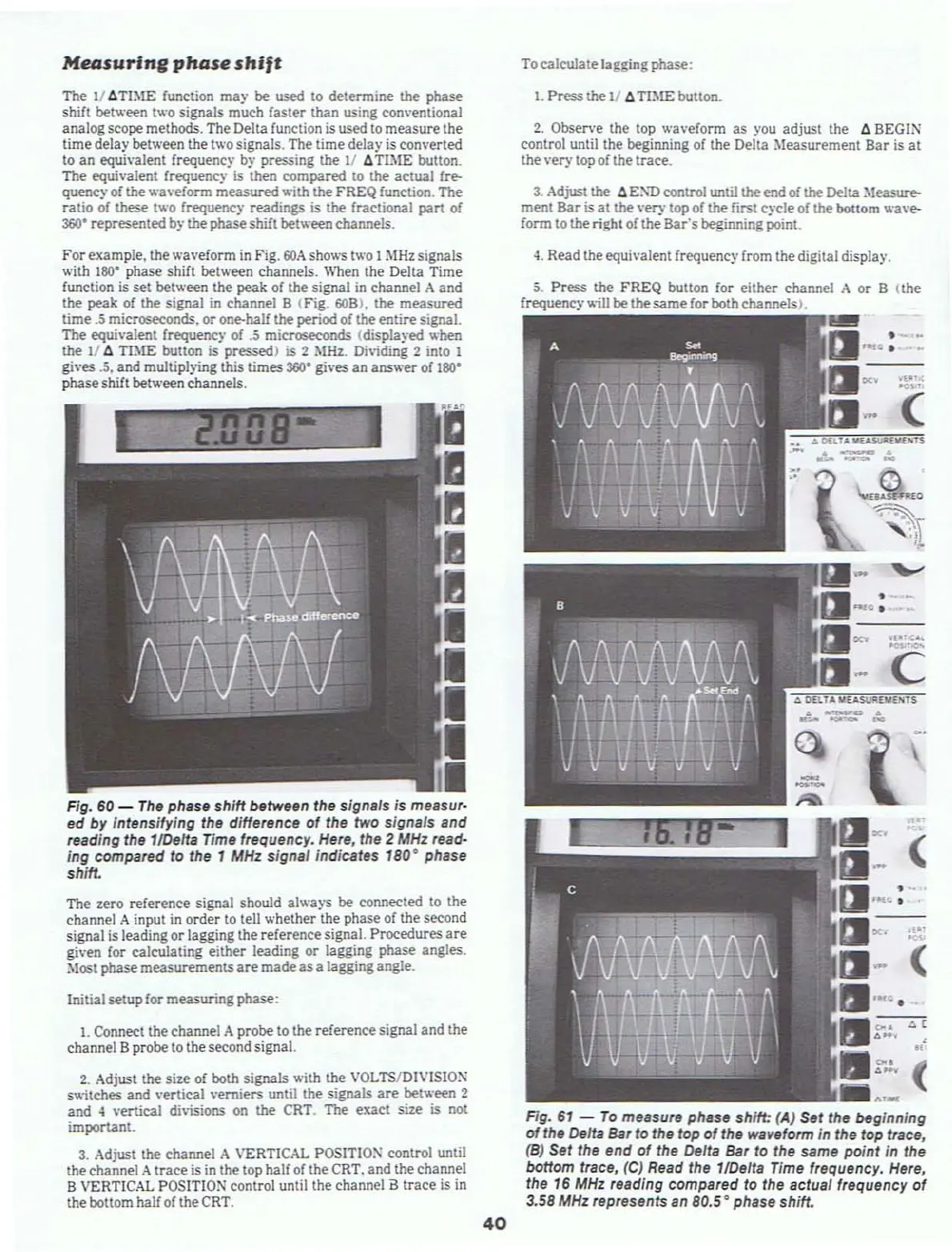
Fig.
61
-
To
measure phase shift:
(A)
Set the beginning
of
the Delta Bar to the top
of
the waveform in the top trace,
(B)
Set the end
of
the
DeUa
Bar to the same
point
in the
bottom trace,
(C)
Read the 1/Delta Time frequency.
Here,
the
16
MHz
reading compared to the actua' frequency
of
3.58
MHz
represents an
80.5·
phase shift.