bunons select the vertical
or
horizontal video s
.....
eep rate. The
second procedure
al1o\\"5
the composite video signal to be
expanded to see mo~ detail
near
the back porch of the vertical
or
horizontalsync information.
It
is normal for the \\'a\'eform
at
the \'ideo detector of a tele-
\'ision receiverto
appear
thicker on
an}'
\\;deband scope than
on
a lower frequency oscilloscope. The wide frequency response
of
the \'ertical amplifiers
of
the
SC61
.....
ill respond to the 45.i5
~tHl
IF
carrier
passing through the detector. This IF signal will not
appear
on
a
lo
.....
er
frequency oscilloscope because the oscillo-
scope's vertical amplifiers filter out the IF
carrier.
The IF
signal
does not affect the
TV
receiver's picture because the
limited \;deoamplifier frequenc}' response
~moves
thesignal.
"ideo
presets
The
TnlEBASE·FREQ
witch
activates
the
two
\;deo
preset
pushbuttons when set
to
the
video preset (bottom) position, The
SC61
displays two cycles
of
the vertical field
rate
or
two
c}'c1es
of
the horizontal line
rate
with the VIDEO VERT
or
VIDEO
HORIZ button depressed and the vernier calibrated. Rotating
the
vernier counterclock\\ise displays more cycles. Pulling the
HORIZ
POSITIO;-;,
control expands any part
of
the signal ten
times.
The \'ideo
preset position
of
the
TI~1EBASE-FREQ
s\\;tch auto-
matically selects the
"n-"
trigger
mode_
no
matter
where the
TRIGGER
~lODE
s\\;tch is set. This simplifies trigger setup
.....
hen it is necessary to alternately
measure
\-ideo and non-\'i.deo
signals
as
the TRIGGER
~IODE
s\\itch may be left
in
the
"Auto"
or
the
"~onn"
position (or the
\'i.deo
and non-\ideo
signals.
Moving the TI:'o1EBASE·FREQ s
....
;tch
to
the video
preset posilion automatically o\'errides the TRIGGER
:'o10DE
switch to select the "TV" trigger mode. SWitching the
TI~tE,
BASE·FREQ s
.....
itch out of the video preset position automati·
call)' returns the control
of
the trigger circuits to the TRIGGER
MODEsv,itch_
To
viev--
composite video signals:
1.
Apply the desired signaHsl to the vertical
input's)
and
select thedesired display pushbuttons,
2.
Set
the
TIMEBASE-FREQ s
....
itch
to
the
"VIDEO
PRESET'
position,
3,
Select the desired TRIGGER SOURCE switch position.
4.
Set the TRIGGER POL4.RITY switch to thecorrect position
to
agree v,;th the direction of the sync pulse,
"-"
for positive-
going
sync
or
"-"
for negath'e-going sync.
5.
Press
the VIDEO VERT pushbutton to \;ev.- signals
at
the
\'ertical rate.
or
the
VtOEO HORIZ pushbutton to view signals
at
the horizontal rate.
Using
the
TDlEBASE-FREQ
s\\;tch
to view video signals
The video sync
separators
may be used
....
ith
any
of
the cali-
brated s
.....
eep positions
of
the TIMEBASE-FREQ s
....
itch
b)'
s\\'i.tching
the TRIGGER
MODE
s
.....
itch to the "TV" position.
The TIMEBASE-FREQ s
.....
itch is generally used
.....
hen time
measurements must
be made on a portion
of
the composite
video signal. or
.....
hen the
area
follo
.....
ing \'ertical
or
horizontal
sync must be expanded to \·ie
.....
detail
in
the blanking intervals.
This feature
allO""'"5
the VIRS
or
VITS
signal (in
the
\'ertical
blanking
intel"'\'all
or
the
color burst signal (in the horizontal
blanking
inten-aJ.) to be expanded.
The selection
of
the \·ertical
or
horizontal sync
separators
is
automatically made by the TIMEBASE·FREQ s
....
itch.
All
s
.....
eepspeeds
in
the
"m
sec" range use the \'ertical sync separa-
tor, andall sweep
speeds
in
the
"u
sec"
range use the horizontal
sync separator.
To
\'i.e
.....
composite
\'i.deo
signals:
1. Apply the desired signai(s) to the vertical inputlsl and
select
the
desired display pushbuttons.
2.
Set the TRIGGER
:'oIOOE
s\\itch to the
"n'"
position.
3,
Select the desired TRIGGERSOURCE switch position.
4. Set the TRIGGER POLo\RITY s
.....
itch to the correct position
to
agree
.....
ith the direction of the sync pulse ,.+" for positive-
going sync
or"
-"
for negati\'e-going sync.
3.
Select the desired s
.....
eepspeed. remembering that the verti-
cal sync separator is
used
in
all sweep speeds marked
"m
sec"
and the horizontal sync
separator
is used for all s
.....
eep speeds
marked
"u
sec",
NOTE:
The
TRIGGER
LEVEL
conlrol
should
lLtually
be
set
to
the
":ero"
posillon. 1/
the
trace
u not /ull)! rrfggered,
adjust
Ihe
TRIGGER
LEVEL
conlrol/ar
best
triggering.
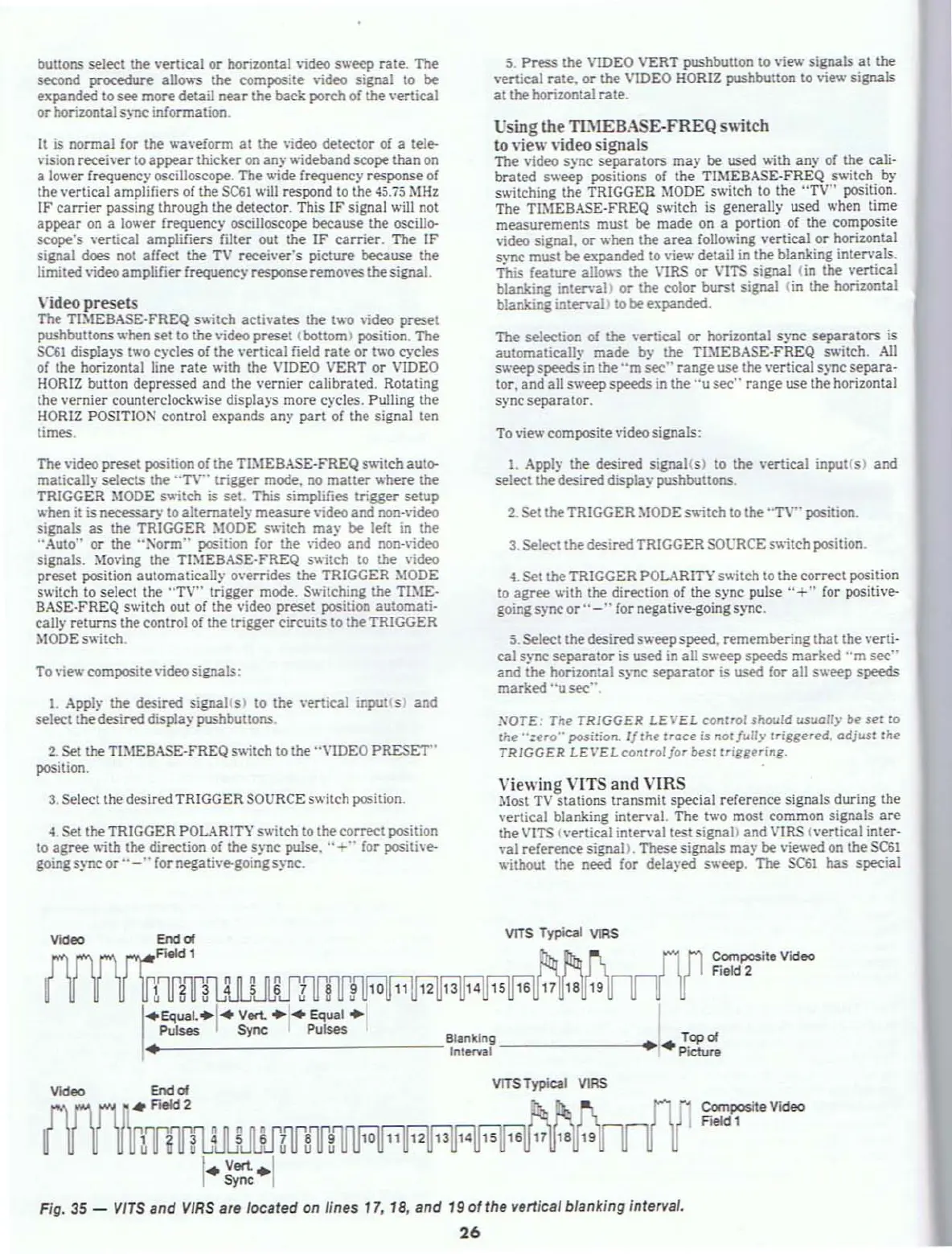
"iewing
VITS
and
VIRS
Most
TV
stations transmit special reference signals during the
vertical blanking
interval. The two most common signals
are
the
VITS
(\'ertical interval test signa\) and VIRS {vertical inter·
\'al reference signal>. These signals
may
be viev.'ed
on
the
SC61
.....
ithout the need for dela}'ed sweep. The
SC61
has special
VlTS
Typical
vtRS
Composite Video
Field
2
amlWJKfmr~
10
.EQuaL·I"
Vert.
.1"
Equal
.1
Pulses
Sync
Pulses
'._----------------Blankin
ll
---------+
Topol
I.
lnt&/'Val·
..
Picture
vrTS
Typical
VlRS
Video
{nlH1JLlMJz'fs'"If'!
I
•
V"'-·1
Sync
Fig.
35
-
vlrs
and
VIRS
are
located on lines 17, 18, and
190'
the vertical blanking interval.
26
Composite Video
Field 1