SecondJy, the digital meter measures fast transitions
on
the
signal which may
not
be readily noticeable
on
the
CRT.
Two
waveform imperfections or interference cause higher peak·to-
peak readings, The interference may be overshoot or other fast
spikes
too
dim to normally
see,
In
addition, random noise spikes
may occur
in
either case, something
not
readily \;sible
on
the
CRT
is causing the meter to read higher,
FrequenC1l
measurements
Pressing the channel A or B
uFREQ""
digital readout button
displays the frequency
or
the signal applied
to
the \'ertical input.
The frequency function is
fully autoranged. so there
is
no
need to
select resolution. read rates, or frequency ranges. The micro-
computer automatically
selects one of
tv.·o
signal conditioning
circuits
for
stable frequency readings.
The
SC61
measures signals from 1
Hz
to
100
MHz. The
5C61
microcomputer automatically selects one of 5e\'en internal
frequency counter ranges, Signals
up
to
100
Hz
ha\'e
two
fuJI
digits after the decimal point for extremely aceurate readings
on
lov.·
frequency signals. Signals from
lOll
Hz
to
lOll
KHz ha\·e.1
Hz
resolution for acr:urate audio measurements. Higher
frequency
signals
are
autoranged to prO\;de six
full
digits
of
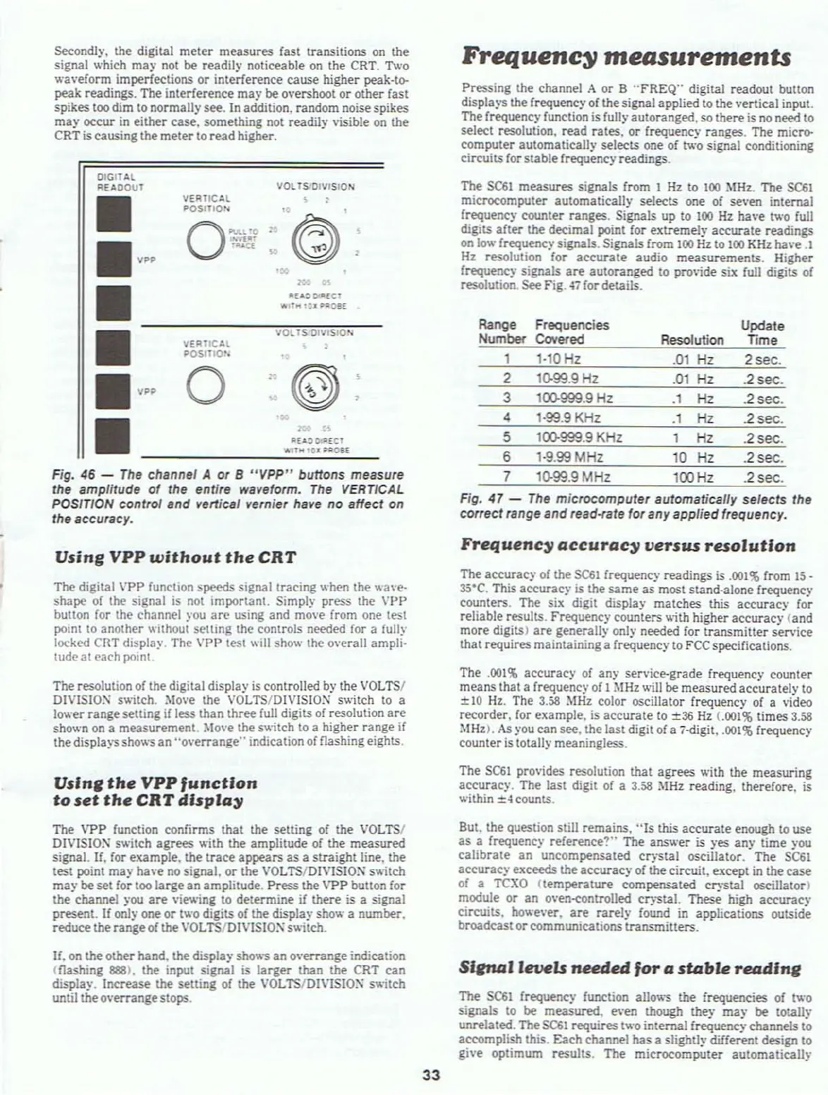
resolution. See Fig.';7 for details.
Fig,
47
-
The
microcomputer
automatically setects the
correct
range and read-rate for any appfied frequency.
OIOITAl
REAOOUT
VOL
TSIOIVISION
•
VERTICAL
, ,
~OSlTIOo.:
..
O~···O
.
©)
,
• v
..
""1_'
'~a
"
.~
=
•
"E.-&~
OlIIlCT
• ·
...
c._au
•
VOL TS OIVIS1O"
VERTICAL
POSltlO',
•
0
r.
<©
,
...
•
••
.~
~
"UI)OPllCI
.11
..
lel
HOlE
Fig.
46
-
The
channel A or B
"VPP"
buttons measure
the amplitude
of
the entire waveform.
The
VERTICAL
POSITION control
Bnd
vertical vernier have no affect
on
the accuracy.
Range
Number
,
2
3
4
5
6
7
Frequencies
Cov",ed
1-'0
Hz
'0-99.9
Hz
lQl).999,9 Hz
1·99,9
KHz
'00.999.9
KHz
'·9.99
MHz
'0-99.9
MHz
Resolution
,01
Hz
,01
Hz
.1
Hz
,1
Hz
1
Hz
10
Hz
100Hz
Update
TIme
2
sec,
.2 sec.
.2
sec,
.2
sec,
2 sec.
,2
sec.
.2
sec,
Vsing
VPP
without
the
CRT
Tht'!
digital VPP function speeds signallracing when the wa\'e·
shape of the signal
is
not
important. Simply press the
\'pp
button
for
the channel
you
are
using and mo\'e from one test
pomt
to
another
Without
settmg the controls needed for a fully
locked
CRT
display The
\'PP
test
will
show the overall ampli·
tude at
eaC'h
point.
The resolution of the digital display
is
controlled
by
the
VOLTS/
DIVISION
s\\;tch. :\love the
VOLTS/DIVISIO~
switch to a
lower range setting
if
less than three
full
digits
of
resolution are
sho\\'n
on
a measurement.
Move
the switch to a higher range
if
the displays
sh~"S
an "overrange" mdication ofnashing eights.
Vsln,
the
VPP
function
to
set
the
CRT
dlsplo)/
The VPP function confirms that the setting
of
the
VOLTS/
DIVISIO:\ switch agrees ,
..
';th the amplitude
of
the measured
signal.
If.
for example, the trace appears
as
a straight line, the
test point may ha\'e
no
signal. or the VOLTS/DIVISIO:\ s\\;tch
may
be set for
too
large an amplitude, Press the VPP button for
the channel
you
are
\'iewing
to
determine
if
there
is
a signal
present.
If
only one or two digits of the display show a number.
reduce the rangeof the
VOL
TS/DlVISIO:\sv.;tch.
If,
on
the other hand, the displa)'
sh~"S
an ovemmge indication
(flashing
888).
the input signal is larger than the
CRT
can
display.
Increase the setting
of
the VOLTS/Dl\'ISIO:\ sv.;tch
until the o\'errangestops.
33
Frequency
accuracy
versus
resolution
The accuracy of the
SC6l
frequency readings
is
.001
%from
15
_
35°C,
This accurac)'
is
the
same
as most stand·alone frequency
counters, The six digit display matches this
acr:uracy for
reliable results. Frequency counters
v,;th higher accuracy (and
more digits)
are
generally only needed for transmitter service
that requires maintaininga frequenc)' to
FCC
specifications.
The
,001%
accuracy
of
any service-grade frequency
C'ounter
means that a frequency of I
MHz
will
be measured accurately
to
±IO
Hz.
The
3,58
MHz
color oscillator frequency of a video
recorder,
for
example,
is
accurate
to
±36
Hz
(.001%
times
3,58
:\tHz>,
As
)'ou
can see. the last digit
of
a 7-digit, ,001$ frequency
counter
is
totally meaningless.
The
SC61
provides resolution that agrees with the measuring
accuraC')', The last digit of a
3.58
:\lHz reading. therefore,
is
within ±4 counts,
But, the question still remains,
"Is
this accurate enough
to
use
as a frequency reference'?"" The answer is )'es any time you
C'alibrate
an uncompensated clj"Stal oscillator. The
SC61
accurac)' exceeds the accuracy of the circuit, except
in
the case
of a
TCXO
(temperature compensated
cr)"StaJ
oscillator)
module or
an
oven-eontrolled cr)"Stal. These high aceuracy
circuits, howe\'er,
are
rarely found
in
applications outside
broadcastorcommunications transmitters.
Siena
I
levels
needed
for
0
sta"'"
readlne
The
SC6l
frequency function allo
....
,so
the frequencies of
tv.·o
signals
to
be
measured. even though they may
be
totally
unrelated, The
SC61
requires 1
....
·0
internal frequenc)' channels to
accomplish
this, Each channel has a slightly different design to
give optimum results. The microcomputer automatically