It
may be necessary to use a special clip (like the one sho"
..
n in
Fig.
18)
when connecting to an integrated circuit. These clips
are
available
in
a variety of sizes and styles for different
Ie
packages. Pomona and E-Z
Hook,
for example. have clips
designed for
14.
16,2';. and .;0 pin ICs. These clips
are
usually
availablethrough local electronicsupply houses.
Fif}. 18 -
IC
test clips provide secure connections to
IC
pins with little chance
of
shorting adjacent connections.
Test probe ground connectors
Each
39G183
comes 'l.;th two ground leads and a ground clip.
It
is ,-ery important that you use the shortest possible ground con-
nector
.....
hen
working
in
high frequency circuit
or
circuits that
produce
square-wavesignals
voith
fast risetime. The inductance
of
extra
ground lead length
....
i1l cause distortion in these signals.
The
long
02")
ground lead
must
only be
used
when measuring
low frequency signals.
It
is always necessary to ground each probe to prevent inter-
ference
or
other
.....
avefonn distortion
on
high frequency signals.
The ground connection should be made
as
close to the test point
as
possible because the extea inductance
of
a printed circuit
board
or
chassis
....
iring
....
ill
have the
same
effect on the display-
ed signal
as
the longerground leads:
.....
avefonn distortion.
The small ground
dip
should be
used
.....
hen making tests
in
digital stages. The small size is designed for easy connection
.....
hen the spring'loaded tip is removed. The clip
is
made of
spring
steel to allo
.....
connections
to
the closely spaced pins
of
an
Ie.
And, above all. the length
of
the clip
is
the smallest possible
to
preventsignaldistortionon fast rise-timesignals.
Fig. 19 -
The
ground clip provides the shortest possible
ground connection and
a convenient way to connect to
IC
pins.
18
Use
care
.....
hen removing a ground lead from the probe. The
plasticstrain-reliefcollar surrounding the
probe ground connec·
tion rotates. and must be set to center the ground connector
in
the rectangular slot before attempting to remove the connector.
Failure to center the connector in the slot before pulling the
connector
may
result
in
a broken ground lead
or
plastic steain-
relief
collar.
Fig.
20
- Make sure the ground clip Is centered
In
the
strain relief hole before trying
to remove the clip.
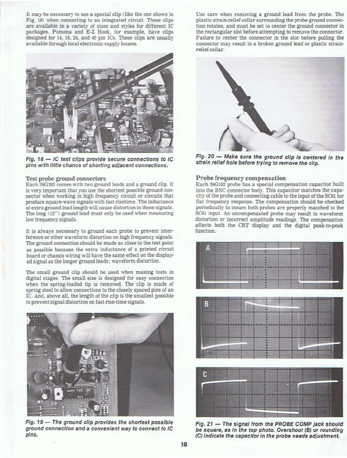
Probe
frequenc)' compensation
Each
39G183
probe
has
a special compensation capacitor built
into the
BXC
connector body. This capacitor matches the
capa·
city
of
the probe and connectingcable to theinput of the
SC61
for
flat
frequency response. The compensation should be checked
periodically
to insure both probes
are
properly matched to the
SC61
input. An uncompensated probe
may
result
in
.....
a
...
eronn
distortion
or
incorrect amplitude readings. The compensation
affects
both the CRT display and the digital peak·tl>peak
function.
Fig.
21
-
The
signal from the
PROBE
COMP
Jack
should
be
square,
8S
In the top photo. Overshoot
(B)
or rounding
(e) indicate the capacitor in the probe needs adjustment.