c
J
R"""'"
od
11111
,
•
Signal
,
Tape
Travel
\
J
-
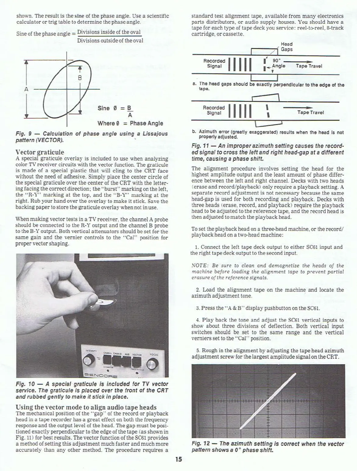
Fig. 12 -
The
azimuth setting is correct when the vector
pattern
shows a 0
0
phase shift.
To
set the playback head
on
a thr1!e-head machine.
or
the record!
playback headon a two-head machine:
5. Rough
in
the alignment by adjusting the
!ape
head azimuth
adjustment
screw for the largestamplitudesignal on the CRT.
4.
Play
back the tone and
adjust
the
SC61
vertical inputs to
show about three divisions
of
deflection. Both vertical input
switches should be
set
to the
same
range
and the vertical
verniers set
to
the
"Cal"
position.
3.
Press
the
"A
&
B"
display pushbutton
on
theSC61.
2. Load the alignment tape on the machine
and
locate the
azimuth adjustment tone.
NOTE:
Be sure
to
clean
and
demagneti=e
the
heads
of
the
machine before
loading
the alignment tape to prevent partial
erosure
of
the reference signols.
standard
test alignment tape. available from
many
electronics
parts
distributors,
or
audio supply houses.
You
should have a
tape for
each
type
of
tape deck )'ou service; reel·te-reel,8-track
cartridge.
or
cassette.
b.
Azimuth error
(grutly
eltlggerlted)
results when
thl
held
Is not
proper1y
IdJusted.
Fig.
11
- An improperazimuth setting causes the record-
edsignal to
cross
the leftand right head-gap
at
a different
time, causing
a phase shift.
The alignment procedure involves setting the head for the
highest amplitude output and the least amount of phase differ-
ence between the left and right channel. Decks with two heads
(erase
and record/playback) only require a playback setting. A
separate
record adjustment is not necessary because the
same
head-gap is used for both recording and playback. Decks with
three heads (erase, record,
and
playback) require the playback
head
to
be adjusted
to
the reference tape. and the record head is
then adjustedto match the playback head.
H-ad
,--/"""[
G,p,
---:-:-:-:-.::=;:::::;:--:-
R~:~jd
11111
:+r;,e
Ta~Travel
I
,----
I.
The
head
g.p.
should
be
exactly perpendicular to
the
edge
of the
~"'.
1. Connect the left tape deck output to either
SC61
input and
the right tapedeck output to the second input.
--
f
8
/
/
/
,/
s
-
r7
A
U
ShOVoi1.
The result is the sine
of
the phase angle. Use a scientific
calculator or trig table
to
determine the phase angle.
Sine
of
the phaseangle = Divisions inside
of
theoval
Divisions outside of theo\'al
Vector
graticule
A special graticule overlay is included
to
use when analyzing
color
TV
receiver circuits with the vector function. The graticule
is
made
of
a special plastic
that
will cling to the CRT face
without the need of adhesive. Simply place the
center
circle
of
the special graticule
over
the
center
of
the CRT with the letter·
ing facing the correct
direction; the
"burst"
marking
on
the left.
the
"R·V"
marking
at
the top.
and
the
"B-V"
marking
at
the
right. Rub )'our hand over the overlay to make it stick. Save the
backing
paper
to storethe graticule overlay when not in use.
Fig. 10 - A special graticule is included for
TV
vector
service.
The
graticule
is
placed over the front
of
the
CRT
and rubbed gentfy to make it stick in place.
Using
the
vector
mode to
align
audio
tape
heads
The mechanical position
of
the
"gap"
of
the record
or
playback
head in a tape recorder has a
great
effect
on
both the frequency
response and the outpulle.·el of the head. The
gap
must be posi·
tioned exactly perpendicular to theedgeof the tape
(as
shown
in
Fig.
11)
for best results. The \'ector function of the
SC61
provides
a methodof setting this adjustment much faster and much more
accurately than
any other method. The procedure requires a
When
making vector tests
in
a
TV
receiver. the channel A probe
should be connected
to
the
R·
V output
and
the channel B probe
to
the B·Y output. Both vertical attenuators should be set (or the
same
gain
and
the vernier controls to the
"Cal"
position for
proper vector shaping.
ina e =B
A
Where 0 =Phase Angle
Fig. 9 - Calculation
of
phase angle using a Ussajous
pattern
(VECTOR),
15