3.
Adjust the channel A VERTICAL POSITION control until
the trace lies
on
the horizontal centerline
of
the
CRT.
ZAXISINPur
4.
Pull the channel A VERTICAL POSITION control
to
activate the invert function.
Be
sure
you
do
not
change the
setting
of
the control
as
it
is
pulled.
5.
If
the trace moves. adjust the INVERT
BAL
control to
return it
to
the centerline.
6.
Carefully push the channel A VERTICAL POSITION
control back to the non-im'erted position.
If
there is a change
in
trace movement, repeat steps 3 through 6 until there
is
no
further improvement.
NOTE:
The
INVERT
SAL
control
is a 100turn
potentiometer.
A signal applied to the Z
AXIS
I~-PUT
connector
on
the
rear
panel intensifies or blanks the trace. A positive signal
of
5 volts
causes the trace to blank. The direct-coupled input allows modu-
lation with any signal from
DC
to
5 MHz.
Do
not
apply more than
35
volts
<DC
+ Peak
AC)
to the direct-
coupled input. Possible damage
to
the amplifier may result
if
a
largeramplitude is applied.
NOTE:
Th~
Z
AXIS
INPUT
signal
leads
the
channel
A
ar
B
vertical
input
by
;0
nanoseconds
due
to
the
signal
delay
line
in
the
vertical
amplifiers.
Consider
this
delay
when
using Z
AXIS
modulation
for
critical
timing
tests.
Rear
panel
'uses
and
connectors
Fuse
replacement
,------WARNING
------,
Always replace the protective fuses with the correct
type
and rating.
Any
other fuse type
or
rating may
cause internal damage to the
SC61
or
create a fire
or
safety hazard. Using an improper fuse type or rating
\'oids
all
warranties.
AcceuoJ'31
(output)
lack
The small pin-jack on the
rear
of
the
SC61
provides an unregu-
lated DC power supply output to power accessories, such as the
PR47
600
MHz
Prescaler. The output voltage is between
12
and
15
volts DC, with a maximum output current
of
100
rnA.
An
accessory connected to the
BNC
input connectors uses the
ground
of
the connector
as
the negative return path. Ground
isolated accessories through the
GRQUr..."D
jack on the front
panel.
The
digital
readout
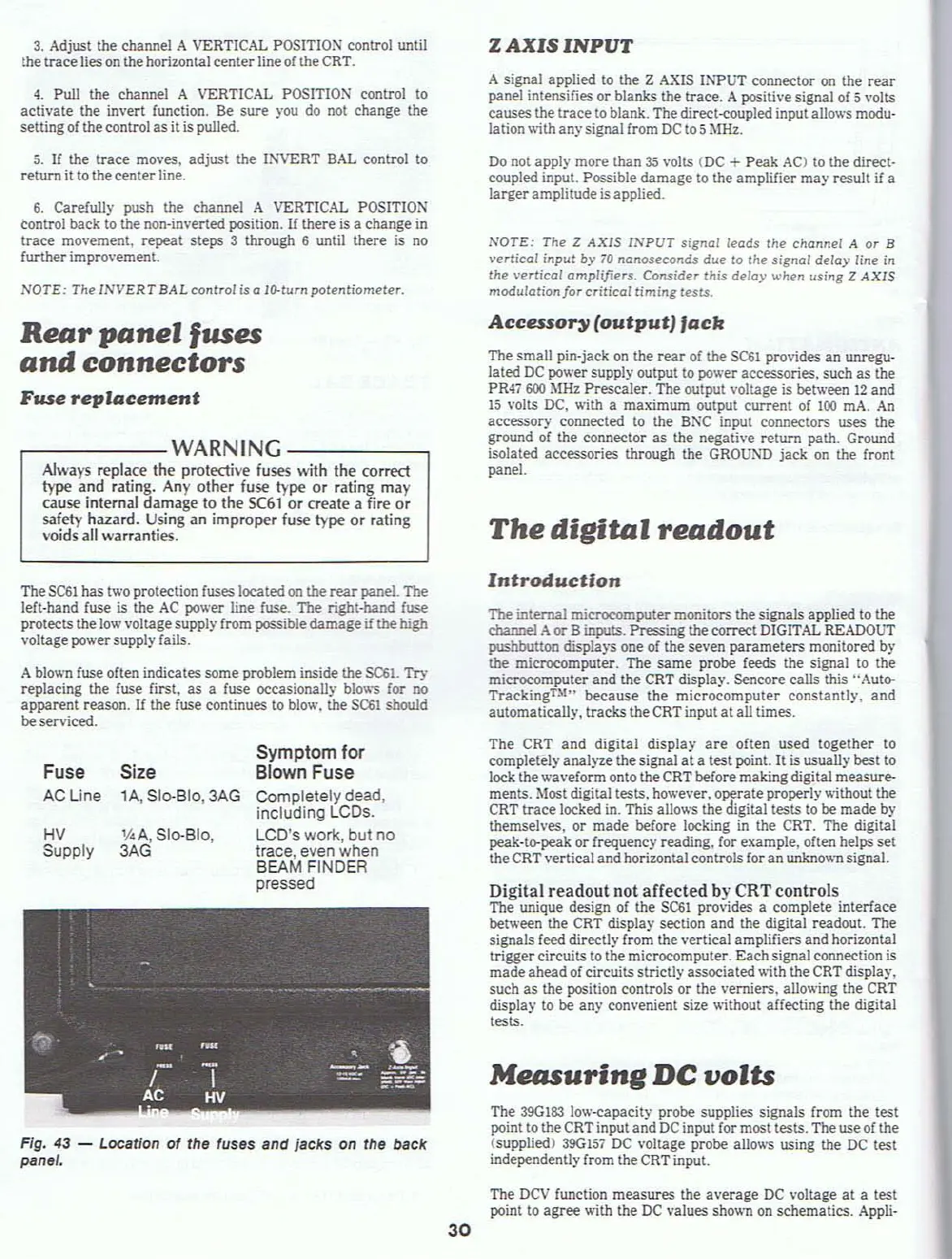
Fig. 43 - Location of the fuses and jacks on the back
panet.
A
blov.'I1
fuse often indicates some problem inside
the
$C61. Try
replacing the fuse first,
as
a fuse occasionally
blow'S
for no
apparent reason.
If
the fuse continues to blow. the
S(:&1
should
beserviced.
The
SC61
has two protection fuses located
on
the
rear
panel. The
left-hand fuse is the
AC
power line
fuse_
The right-band fuse
protects the
low
voltage supply from possible damage
if
the
high
voltage powersupply fails.
Digital readout not aHected by CRT controls.
The unique design of the
SC61
provides a complete tnterface
between the
CRT
display section and the digital readout. The
signals feed directly from the vertical amplifiers and horizontal
trigger circuits to the microcomputer. Eachsignal connection is
made ahead
of
circuits strictly associated with the
CRT
displa)'.
such as the position controls or the verniers. allowing the
CRT
display to be any convenient size without affecting the digital
tests.
The
390183
low-capacity probe supplies signals from the test
point to the
CRT
input and
DC
input for most tests. The use of the
(supplied) 390
157
DC voltage probe allows using the
DC
test
independently from the
CRT
input.
Measuring
DC
volts
Introduction
1be
internal microcomput.e.r monitors the signals applied to the
channel
Aor
Binputs. Pressing the correct
DIGITAL
READOUT
pushbutton
displaY'S
one
of
the seven parameters monitored by
the microcomputer. The same probe feeds the signal to the
microcomputer and the
CRT
display. Sencore calls
this"
Auto-
Tracking
U
'"
beeause the microcomputer constantly. and
automatically, tracks the
CRT
input at all times.
The CRT and digital display
are
often used together to
completely analyze the signal
at
a test point.
It
is usually best to
lock the waveform onto the
CRT
before making digital measure-
ments. Most digital tests. however.
o~rate
properly
vt'ithout
the
CRT
trace locked in. This allows the digital tests to be made by
themselves. or made before locking
in
the CRT. The digital
peak-to-peak or frequency reading. for example, often helps set
the CRT vertical and horizontal controls for an
unkno\\'I1
signal.
Symptom for
Blown Fuse
Completely dead,
including LCOs.
LCD's work, but no
trace, even when
BEAM FINDER
pressed
1/4
A,
510-810,
3AG
Size
lA,
SloBID,3AG
HV
Supply
Fuse
AC Line
30
The
DCV
function measures the average
DC
voltage
at
a test
point
to
agree with the
DC
values shown
on
schematics.
Appli-