Delta
peak·to-peak
Delta
peRk.tOopeak
and
IIldeosll/naJs
The boP?\, function measures the
amplitude
of
the portion
of
the
waveform intensified
b~'
the Delta Bar. The
amplitude
of
channel A
or
B
may
be measured
b~'
depressing the appropriate
bunon. The digital
circuits
measure
all parts
of
the intensified
signal.
Some applications
may require the Delta Peak-to-Peak function
10
isolate extraneous signals from
an
amplitude reading
..
.\
w3\'eform \\;Ih an overshoot
or
other Interference. £orexample.
1,l,;11
Include the
interference
in the 10lal peak-to-peak value.
e\"en
though the mterference
has
no aHeet on thecircuit. Simply
use
the
[Rita
Bar
10
intensify all
parts
of the waveform t')'Cf'pl
lheInterference
10
measure
the effeclh'eamplitudeof the rest
of
thesignal
To measurethe
PPVof
a part
of
a signal:
1.
Press the
CH
A
dPPVor
CH
B.6
PPV
bunon.
2.
Adjust the INTENSITY control for the desired contrast
bet
......
een the Delta
Barand
the background.
3.
Adjust the 6.BEGIN and
dENDcontrols
until the
area
to be
measured is intensified.
Delta peak-tf>peak readings of
....
ideo signals require the use of
the special "'ideo
sync
separators.
The
sync
separators
eliminate "'ertical s
...
-nc
interference
in
addition to their main
function
of
producing a stable trace.
The
Delta peak-ta-peak test
rna"
show an
error
.....
hen attempting to
measure
part
of a hori-
zontal line
~;th
"'ertical interference. Consider the follov.;ng
example
to understand
.....
hy this is true.
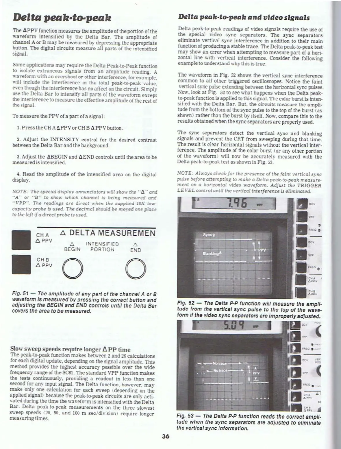
The
wa
....
eform
in
Fig.
52
shows the
....
ertical sync interference
C<lmmon
La
all other triggered oscilloscopes. Xotice the faint
.,·ertical sync pulse extending between the horizontal sync pulses.
Xov.',
look
at
Fig.
52
to see whal happens when the Delta peak.
tf>peak function is applied to this signal. The color burst is inten-
sified
~ith
the Delta Bar. But. the circuits measure the ampli-
tude from the boltom
oi the sync pulse
to
the top of the burst
(as
shown)
rather
than the burst by itself.
No
.......
compare this to the
resultsobtained
when the sync
separators
are
properly used.
The sync
separators
detect the
....
ertical sync
and
blanking
signals and prevent the CRT from sweeping during that time.
The result is clean horizontal signals without lhe .,'ertical inter-
ference. The amplitude
of
the color bursl (or
any
other portion
of
the wa
....
eform) will now be accurately measured
......
ith the
Delta peak·tf>peak test
as
shown
in
Fig.
53.
'"
,.oro.
-
•
~
..
Fig,
52
-
The
Defts
p.p
function will measure the ampli.
tude from
the vertical
sync
pulse
to
the top
of
the wavtt-
form if the video sync separators are improperly adjusted.
-
: (
NOTE:
Al""'ays checl!:
for
the
presence
of
Ihe
foint
\'erti("a/
sync
pulse
before
attempting
fO
make
a
Delta
peak·
to-peal!:
measure.
ment
on a
hori:ontal
....
ideo ""'aveform.
Adjusl
the
TRIGGER
LEVEL
conlrol
until
the
\-ertical
interference
is
eliminated.
Fig. 53 -
The
Delta p.p function reads the correct ampff-
tude when the
sync
separators are adjusted to eUm/nBte
the vertical sync information.
II
CH A
t;. DELTA MEASUREMEN
6PPV
'"
TE
SIFIED
'"
BEGIN
PORTIO
END
II
CHB
0 0
6 PPV
Slow sweep speeds require longer I:i
PP
time
The peak-tf>peak function makes between 2 and
26
calculations
for each digital update. depending
on
thesignal amplitude_ This
method provides the highest accurac)' possible over the
...
1';de
frequency
range
of
the
SC61.
The
standard
VPP
function makes
the tests continuously,
providing a readout
in
less than one
second for
any
input signal. The Delta function. howe
....
er.
may
make onl
....
one calculation for
each
sweep (depending
on
the
applied
signal> because the peak-ta-peak circuits
are
only actio
....
ated
during the time the wa
...
·eform is intensified with the Delta
Bar. Delta peak·tf>peak measurements on the three slo
.....
est
s
.....
eep speeds
(20.
SO.
and
100
m sec/division) require longer
measuring times.
NOTE:
The
special
display
annuncialars
will
sho"'"
Ihe
"d"
and
"A"
or
"B"
10
show
which
channel
is
being
measured
and
"VPP··.
The
readings
are
direct
when
the
supplied
lOX
fo'\ol.··
capacity
probe
is used.
The
decimal
should
be
mo\'t'd
one
place
to
fhe left
if
a
direct
probe
is
used
4.
Read the amplitude of the intensified
area
on
the digital
display.
Fig. 51 -
The
amplitude
of
any part
01
the channel A
or
B
waveform
is
measured by pressing the correct button and
adjusting the BEGIN and
END
controls untif the Defta Bar
covers the area to
be measured.
36