1. Apply the signals to the t
.....
o
SC61
inputs.
2.
Depress the VECI'OR display pushbutton.
3.
set
the channel a
L'--PUT
COUPLING s
....
;tch
to the
"ground"
position and the channel A
Ii'.--PUT
COlJPLIr\G sv.;tch to the
..
AC"
position.
To
measure
thephasedifferenceusing the VECT'OR mode:
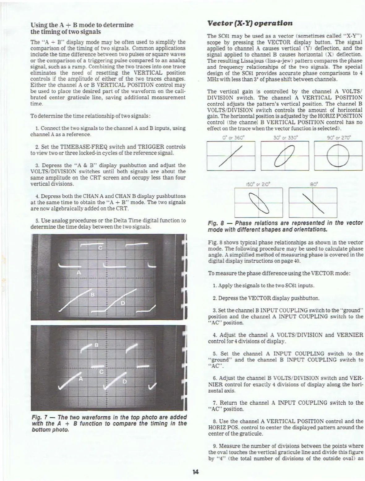
Fig_
8 shows typical phase relationships as shown in the vector
mode. The foUov.ing procedure
may
be
used to calculate phase
angle. Asimplified method of
measuring
phase
iscovered in the
digitaldisplay instructionson page
40.
5. Set the channel A
I:-'"PUT
COlJPLI:\G s
.....
itch to the
"ground"
and
the channel B
1i'."PUT
COlJ"PLI:\G s
....
itch
to
"AC".
Fig. 8 - Phase relations are represented In the vector
mode with differentshapes and orientations.
The vertical gain is controlled by the channel A VOLTS/
DIVISION s
.....
itch.
The
channel A VERTICAL POSITION
control
adjusts
the
pattern's
vertical position. The channel a
VOLTS/DIVISION switch controls the amount of horizontal
gain. The horizontal position is adjusted by the HORIZ POSITlO:\"
control (the channel B VERTICAL
POSITIO:--l
control has no
effect
on
the
trace
when the vectorfunction isselected).
6_
Adjust the channel B VOLTS/D1VISIO=" s
....
itch
and VER-
NIER
control for exaclly 4 di\;sions of display along the hori-
zontal axis.
4.
Adjust the channel A
VOLTSIDIVISIO:--I
and
VER:\IER
control for.; di\isions of displa)'.
Vector
ex-¥)
operation
7.
Return the channel A INPUT COUPLlNG switch to the
"AC" position.
The
SC61
may
be
used
as a \'ector (sometimes called
"X-Y")
scope
by pressing the VECl'OR display button. The signal
applied to channel
A
causes
\·ertieal
(\')
deflection.
and
the
signal applied to channel
a causes horizontal
(X)
deflection.
The
resulting Lissajous (liss·a·jev.·)
pattern
compares
the phase
and
frequenc)' relationships of the
tv.-o
signals. The special
design of the
SC61
provides
accurate
phase comparisons to 4
MHz
....
ith
less
than
3·
of phase shift between channels.
5.
se
analog procedures
or
the Delta
Time
digital function to
determine
the
time
delaybetween the two signals.
4.
Depress both the
CHAN
A and
CHAN
adisplay pushbuttons
at
the
same
time to obtain the
"A
+
a"
mode. The two signals
are
now algebraicallyadded
on
the CRT.
1.
Connect the two signals to the channel
Aand
B inputs. using
channel
A as a reference.
To determine the time relationship of two signals:
2.
Set the TBtEBAS£-.FREQ switch
and
TRIGGER controls
to
view
tv.-o
or
three
locked-in cycJesofthe referencesignal.
3.
Depress the
"A
&
B"
display pushbutton
and
adjust
the
VOLTS/DIVISION s
....
;tches
until both signals are about
the
same
amplitude on the CRT
screen
and occupy less than four
vertical divisions.
Usingthe A +B mode to determine
the
timing
of
two
signals
The
"A
-
B"
display mode
may
be
often used to simplify the
comparison
of the timing of two signals. Common applications
include
the
time
difference between two pulses
or
square
waves
or
the comparison of a triggering pulse
compared
to an analog
signal, such as a
ramp.
Combining the two traces into one
trace
eliminates the need of resetting the VERTICAL position
controls
if the amplilUde of
either
of the two traces changes.
Either
the
channel A
or
B VERTICAL
POSITIO~
conlrOl
may
be used 10 place the desired
part
of the waveform on the cali-
brated
center graticule line. saving additional
measurement
time.
Fig. 7 -
The
two waveforms
In
the top photo are added
wnh the A + B function to compare the timing in the
bottom photo.
8.
Use the channel A VERTICAL POSITION control
and
the
HOR1Z
POS. control
to
center
the displa)·ed
pattern
around the
center
of the graticule.
9.
Measure the
number
of
divisions between the points
.....
here
the o\'al touches the vertical
graticule
line and
di\;de
this figure
by
";l"
(the total
number
of
di\isions
of the outside ova))
as
14