TRIGGER
SOURCE MODE
rf.>/erf.>nced
to
the
AC
line. The
actual
vertical
role
for
TV
signars
is 59.94 Hz
for
interlaCf.>d
signals
or
60.05
H:
for
non-inlerloced
signals.
AC
LINE
•
•
EXT
CH
A.
CH B
•
o
POLARITY
+
o
AUTO
NORM •
TV
·0·
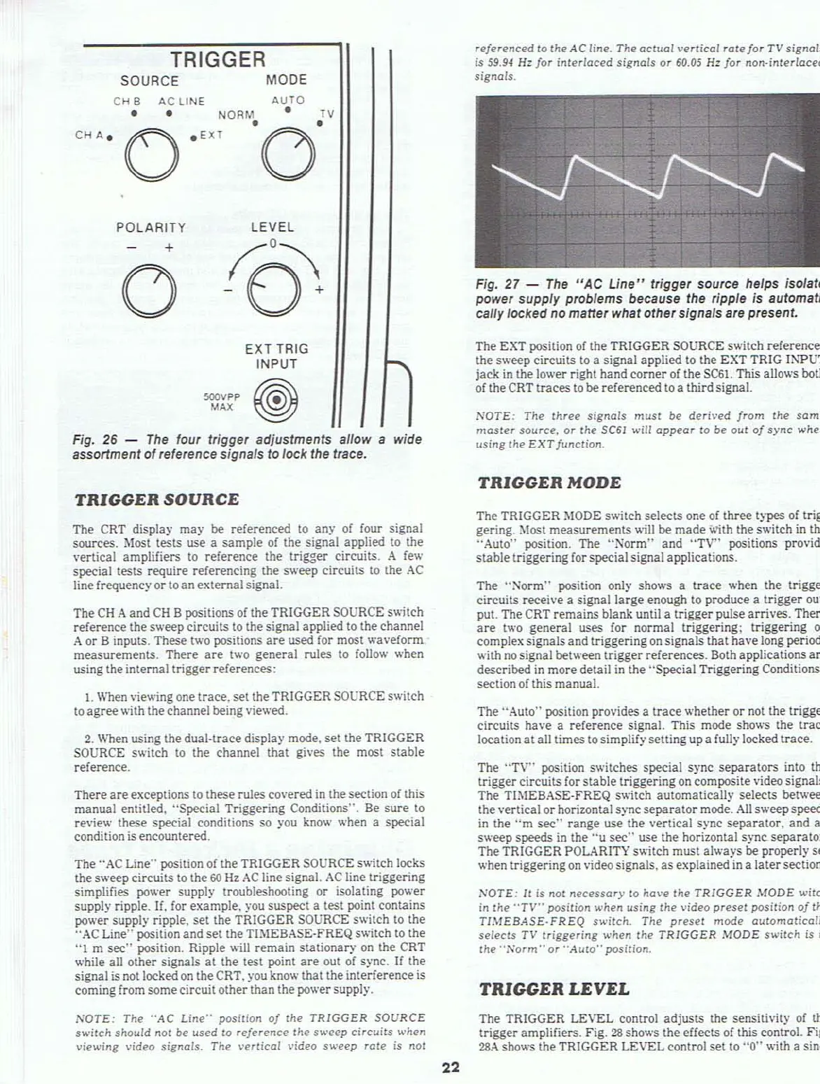
Fig. 27 -
The
"AC
Line"
trigger source helps isolate
power supply problems because the ripple
is automati·
cally locked no matter what other signals are present.
EXT TRIG
INPUT
~~p
~
Fig.
26
-
The
four trigger adjustments allow a wide
assortment
of
reference signals to lock the trace.
TRIGGER
SOURCE
The
CRT
display may
be
referenced to any of four signal
sources.
Most tests use a sample of the signal applied
to
the
\'ertical amplifiers to reference the
trigger circuits. A few
special tests require referencing the s
.....
eep circuits to the
AC
line frequency
or
to
anexternal signal.
The
CH
Aand
CH
B positions of the TRIGGER SOURCE switch
reference the s
.....
eep circuits
to
the signal applied [0 the channel
A
or
B inputs. These two positions
are
used for most
.....
aveform
measurements. There
are
t
.....
o general rules to
follow
.....
hen
using the internal triggerreferences:
I.
When viewing one trace. set the TRIGGER SOURCE switch
to agreewith thechannel being viewed.
2.
When using the dual-trace display mode, set the TRIGGER
SOURCE
switch
to
the channel that gives the most stable
reference.
There
are
exceptions
to
these rules covered
in
thesection
of
this
manual entitled. "Special Triggering Conditions". Be sure
to
review these special conditions so you know
.....
hen a special
condition
is
encountered.
The "AC
Line"
position of the TRIGGER SOURCE s
....
itch
locks
the sweep circuits to the
60
Hz
AC
line signal.
AC
line triggering
simplifies
power supply troubleshooting
or
isolating power
supply ripple.
If. for example. you suspect a test point contains
power supply ripple. set the TRIGGER SOURCE switch
to
the
"AC Line" position and set the TIMEBASE·fREQ switch to the
"I
m
sec"
position. Ripple will remain stationary
on
the CRT
.....
hile all other signals
at
the test point
are
out
of
sync.
If
the
signal
is
not
locked
on
theCRT.
)"ou
know that the interference
is
comingfrom somecircuit otherthan the power supply.
,'I,'OTE:
The
"AC
Line"
position
oj
the
TRIGGER
SOURCE
switch
should
7101
be used
10
reference
Ihe sl<'eep
circuits
when
viewing
video
signals.
The
\'errical
\'ideo
swef.>p
rote
is
7101
22
The EXT position
of
the TRIGGER SOURCE s
....
itch
references
the sweep circuits
to
a signal applied to the EXT TRIG
Il'.i"PUT
jack
in
the lower right hand corner
of
the
SC61.
This allows both
of theCRT traces to
be referenced
to
a thirdsignal.
NOTE:
The
Ihree
signals
must
be
derived
jrom
the
same
master
source.
or
Ihe
SC61
will
appear
to
be
Oul
af
sync
when
using
the
EXT
function.
TRIGGER
MODE
The TRIGGER
MODE
s
.....
itch selects one
of
three types of trig-
gering.
Most measurements
.....
ill
be
made v.ith the switch in the
"Auto" position. The "Norm" and
"TV"
positions pro\'ide
stable triggering for special signal applications.
The
":-Jorm" position only shows a
trace
......
hen the trigger
circuits
receh'e a signal large enough to produce a trigger out-
put. The CRT remains blank until a trigger pulse arrives. There
are
two general uses for normal triggering; triggering
on
complex signals and triggeringon signals that have long periods
with
no
signal between trigger references. Both applications
are
described
in
more detail
in
the "Special Triggering Conditions"
sectionof this manual.
The "Auto" position provides a
trace
whether or not the trigger
circuits have a reference signal. This mode shows the
trace
location
at
all times to simplifysetting up a fully locked trace.
The ''TV'' position switches special
sync separators into the
trigger circuits for stable triggering on composite video signals.
The
TI:'oIEBASE·FREQ switch automatically selects between
the vertical
or
horizontal sync separator mode.
All
sweepspeeds
in
the
"m
sec"
range use the vertical sync separator, and all
sweep speeds in the
"u
sec"
use the horizontal sync separator.
The TRIGGER POLARITY switch must always
be properly set
when triggering on video signals. as explained
in
a latersection.
NOTE:
11
is
7101
necessary
to
have
the
TRIGGER
MODE
witch
in Ihe
"TV"
position
when
using
Ihe
vidf.>o
presel
position
oj
the
TIMEBASE·FREQ
switch.
The
presf.>!
mode
automalically
selects
TV
Iriggering
when Ihe
TRIGGER
MODE
switch
is in
the ··
..
'orm
..
or
"Auto"
position
.
TRIGGER
LEVEL
The TRIGGER LEVEL control adjusts the sensitivity of the
trigger amplifiers. Fig.
28
sho
....
'S
the effects of this control. Fig.
28.-\
sho
.....
'S the TRIGGER LEVEL control set to
"0"
with a sine-