Fig. 32 -
The
vertical
sync
information shows
as
a faint
background trace when
the video
sync
separators are not
used
or
improperly set.
Fig. 33 -
The
SC61
has
specialcircuits that eliminate the
vertical sync when viewing video signals
at
the horizontal
rate for
correct Delta p.p readings.
There is one other condition unique to video signals. Many test
points
in
a
TV
receiver
or
video monitor contain the vertical and
horizontal
S)'llC pUlses needed
h)'
the
SC61
for proper triggering.
A
fetA'
points, ho
.....
ever. do not have sync. One example is the
output
of
the chroma bandpass amplifiers. The
low
frequency
sync
pulses
are
removed b)' the filtering action
of
these stages.
Signals
\lithout sync information may not
lock
solidJ)'
on
the
SC61.
Trigger the
SC61
from another test point. such
as
the video
detector
or
sync separator. to provide a stable trigger reference.
The secQnd trigger source
may
be
fed 10 the external trigger
input
or
to the second vertical channel.
Setting
the
TlMEBASE.FREQ
switch
TheTlMEBASE-FREQswitch plays a much less important role
in
most
SC61
measurements compared
to
an analog oscillo-
sctlpe. The digital display provides a direct readout of time
or
frequency for most measurements. eliminating the need for
analog readings. The TIMEBASE·FREQ switch,
and
its
associated
\'ernier control,
are
simply adjusted to show
as
much
or
as
littledetail in the waveform asdesired.
The TlMEBASE-FREQ switch is fully calibrated, allowing the
SC61
to
be
used
as
an
analog oscilloscope
if
desired. The main
use of the frequency markings. however, will
be
to
set
the
TL\lEBASE-FREQ
switch to the correct sweep
rate
to display a
signal
\l;th a known frequency. The following sections cover the
procedures for displaying a waveform, followed by procedures
for maltinganalog measurements
of
timeand frequency.
25
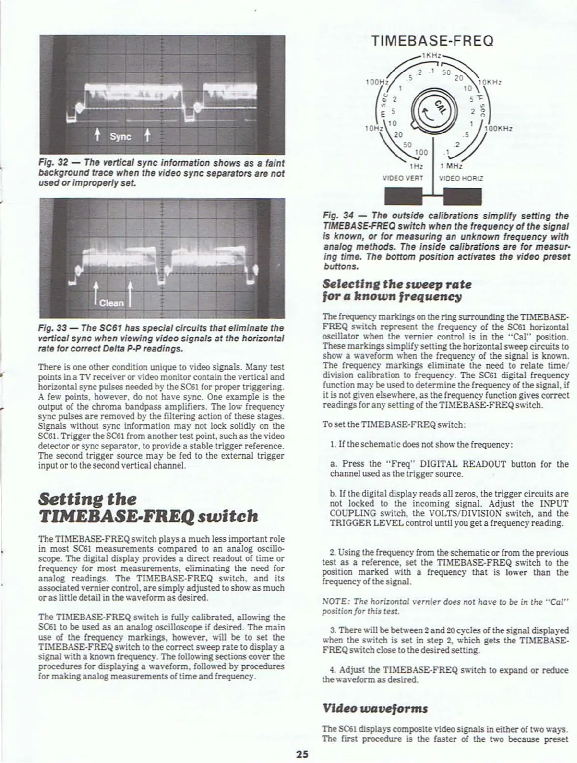
TIMEBASE-FREQ
~"H'~
"7~~2'~r
\t'
~
'''I)
""~~'J-"'
1Hz I
101Hz
VIDEO
VERT
VIDEO HOAIZ
Fig.
34
-
The
outside calibrations simplify setting the
T1MEBASE-FREO
switch when the frequency
of
the signal
is known, or for measuring
an
unknown frequency with
analog methods.
The
inside calibrations are for measur·
ing time.
The
bottom position activates the video preset
buttons.
Selectlne
the
sweep
rate
for
a
known
frequenc)/
The
frequency
markings
on
the ring surrounding theTThlEBASE-
FREQ
s~;tch
represent the frequency
of
the $C61 horizontal
oscillator when the vernier control is
in
the "Cal" position.
These markingssimplifysetting the horizontal
sweeptircuits
to
show a waveform when the frequency
of
the signal is
kno
...
.-n.
The frequency markings eliminate the need to relate time/
di\'ision calibration to frequency_ The
SC61
digital frequency
function
may
be
used to determine the frequency
of
thesignal,
if
it is not given elsev.'here,
as
the frequency function gives correct
readings for an)' setting
of
theTIMEBASE-FREQ s'Aitch.
To set theTL\1EBASE-FREQ switch:
1.
If
theschematicdoes not show thefrequency:
a.
Press the
"Freq"
DIGITAL READOUT button for the
channel used as the triggersource.
b.
If
thedigital display reads all zeros. the trigger circuits
are
not locked to the incoming signal. Adjust the INPUT
COUPLING
switch. the VOLTSIDIVISION switch, and the
TRIGGER LEVELcontrol until you get a frequency reading.
2.
Using the frequency from theschematic or from the previous
test as a reference. set the TH\lEBASE-FREQ s'A;tch
to
the
position marked
\lith a frequency that
is
lower than the
frequency of thesignal.
NOTE: The hori:ontol vernier
does
not
have to
Ot'
in the
"Cal"
position/or this test.
3.
There\lill
be between 2and
20
cycles
of
thesignal displayed
when
the s'A;tch is set in
step
2,
which gets the TIMEBASE·
FREQs
....
;teh
close to thedesiredsetting.
~.
Adjust the TIMEBASE-FREQ sv.;tch to expand
or
reduce
the waveform
as
desired.
Video
waveforms
The
5<::61
displa)"S composite
\;deo
signals in either
of
1\\'0
waJ"S.
The
fltst procedure
is
the
faster of the two because preset