selects which
of
the
two
channels is used to
disp.1ay
a frequency
reading depending
on
which channel "FREQ" button is selected.
and which
inpUt
is used
to
trigger the
CRT
display.
The
most important thing to remember about the main counter
channel
is that the frequency counter reads
correctly
whene\'er
the
CRT display is locked to the incoming signaL Con\'ersel)"
the counter
will
read all
zeros
if
the lrigger circuits
are
not
locked.
TIle auxiliary channel requires
at
least
1.5
major
divisions of
signal
on
the
CRT
for
ae<::urate
measurements. Check theampli-
tude
of
the auxiliary channel
on
the
CRT
to
cooflTID.
thesignal is
large enough to measure. Change the setting
of
the
VOL
TSI
D1VISIO:\,
s~itch
if
the
CRT
amplitude is less than
1..5
major
divisions.
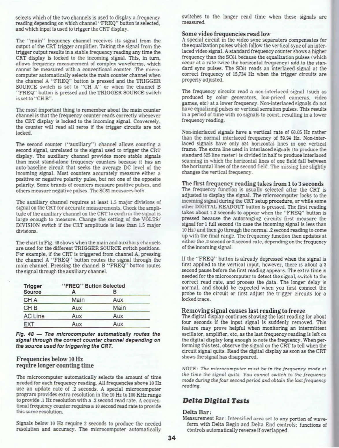
The chart in Fig.
48
shows when the main andauxiliarychannels
are
used for the different TRIGGER
SOURCE
s~itch
positions.
For example, if the
CRT
is triggered from channel
A,
pressing
the channel A
"FREQ"
button routes the signal
through
the
main channel. Pressing the channel
B
"FREQ"
button routes
the signal through the
auxiliary channel.
switches to the longer read time
when these signals
are
measured.
Some video frequencies
read
low
A special circuit in the video sync separators compensates for
the equalization
pulseswhich folio\\' the vertical sync
of
an
inter·
la~
video signal. A standard frequency counter
sho~"5
a higher
frequency than the
SC61
because the equaliz.ation pulses (which
occur at a rate twice the horizontal frequency) add to the stan·
dard sync
pulses. The
SC61
reads an interlaced signal
at
the
correct frequency
of
15.73-1
Hz
when the trigger circuits
are
properlyadjusted,
The frequency
cireuits read a non·interlaced signal (such as
produced by color generators. low·priced cameras. \ideo
games. etc)
at
a
1000'er
frequency.
Non-interla~
signals do
not
have equalizing pulses
or
vertical serration pulses. This results
in
a period of time
....
ith
no
signals to count, resulting
in
a lower
frequency reading.
Xon-inteclaced
signals ha\'e a vertical cate
of
60.05
Hz
cather
than the nonnal interlaced
frequency of 59.s;, Hz. Non·inter-
laced
signals ha\'e
onl~'
52.;
horizontal lines
in
one \'ertical
fcame. The
extra line used in inteclaced signals (to produce the
standard
525
line raster) is di\ided
in
half
to produce interlaced
scanning in which
the
horizontal lines of one field fall betv
..
een
the horizontal lines
of
the second field. The missing line slightly
changes the
\"ertical frequency.
The
first frequenc)'
reading
takes from 1to 3 seconds
The
frequency function is usually selected after the
CRT
is
adjusted to displa)' the signal. The microcomputer locks to the
incomingsignal during the
CRT
setupprocedure, or while some
other
DIGITAL READQtJl' button is pressed. The
fll'St
reading
takes
about 1.2 seconds to appear when the "FREQ" button is
pressed because the autoranging cireuits fiest measure the
signal for
1
full
second (in case the incoming signal is less than
10
Hz) and then
go
through the normal .2 second reading to come
up with the final range. The frequency function then updates
at
either the.2 second or2 second cate. depending
on
the frequency
of
the incoming signal.
If
the "FREQ"
bUlton
is alceady depressed when the signal is
first applied to the vertical input,
hov,,'ever.
there is aboul a 3
second pause before the first reading appears. The extra time
is
needed for the microcomputer
to
detect the signal, switch to the
correct read rale. and
process the
aata.
The longer delay is
nonnal, and should be expected
when you first connect the
probe
lO
the circuit or first adjusl the lrigger circuits for a
locked trace.
Main
Aux
"FREO"
Button Selected
A 8
Trigger
Source
CHA
The
"main"
frequency channel recei\'es its signal from the
output of the
CRT
trigger amplifier. Taking the signal from the
lrigger output results
in
a stable frequency reading any time the
CRT
display
is
locked to the incoming signal. This, in turn,
a11O\\"5
frequency measurement of complex wavefonns, which
cannot
be
measured
~ith
a conventional counter. The
mic~
computer automatically selects the main counter channel when
the channel A
"FREQ"
button is pressed and the TRIGGER
SOURCE
sv';tch is set to "CH
A"
or when the channel B
"FREQ"
button is pressed and the TRIGGER
SOURCE
s~itch
is
set to "CH
S".
The second counter ("auxili8iY") channel
allov.-s
counting a
second signal, unrelated to the signal used to lrigger the
CRT
displa)', The auxiliary channel provides more stable signals
than most stand-alone frequency counlers because it has an
auto-baseline
circuit that
seeks
the a\'ecage
DC
level
of
the
incoming signal.
Most
counters
aC'CW'ately
measure either a
positive or
negath'e polarit)' pulse, but not one
of
the opposite
polarity. Some bcands of
counters measure posith'e pulses. and
others measure negath'e pulses. The
SC61
measures both.
Signals belo\\'
10
Hz
require 2 seconds to produce the needed
resolution
and accuracy.
The
microcomputer automaticaUy
Frequencies below
10
Hz
require longer counting time
Fig.
48
-
The
microcomputer automatically routes the
signal through
the correct counter channel depending on
the source used for triggering the
CRT.
The
microcomputer automatica11)' selects the amount
of
time
needed for each frequency reading.
All
frequencies above
10
Hz
use an update cate of
.2
seconds, A special microcomputer
program provides extra
r!SOlution
in the
10
Hz
to
100
KHz
cange
to
provide.l
Hz
resolution v.;th a
.2
second read cate. Aconven·
tional frequency counter requires a
10
second read rate to prm.ide
this
same
resolution.
Removing signal causes
last
reading to freeze
The digital display continues
sho~ing
the last reading for aboul
four seconds
if
the input signal is suddenly removed. This
feature may prove helpful when monitoring an intermittent
oscillator, amplifier, etc. as the last frequency
reading is left
on
the digital display long enough to note the frequency,
When
per.
fonning this test, observe the signal
on
the CRT to tell when the
circuit signal quits. Read the digital display
as
soon
as
the
CRT
shows the signal hasdisappeared,
NOTE:
The
microcomputer
must
be
in the jrequency
mode
ot
the
time
the
signel
quits.
You cellllot
switch
to
the frequency
mode
during
the four
second
period
elld
obtain
the
fast frequency
reading.
Delta
Digital
Tesu
Delta
Bar:
Measuremenl Bar: Intensified area set to any portion of wa\'e-
fonn
~ith
Delta Begin and Delta End controls; functions
of
controlsautomatically reverse if o\·erlapped.
34
Aux
Main
Aux
Aux
Aux
Aux
AC
Line
EXT
CHB